[0014]In another embodiment, the transmitter included in the presently disclosed
magnetic tracking system employs a
digital tuning technique that compensates for component variation so that precision component values are not required to achieve
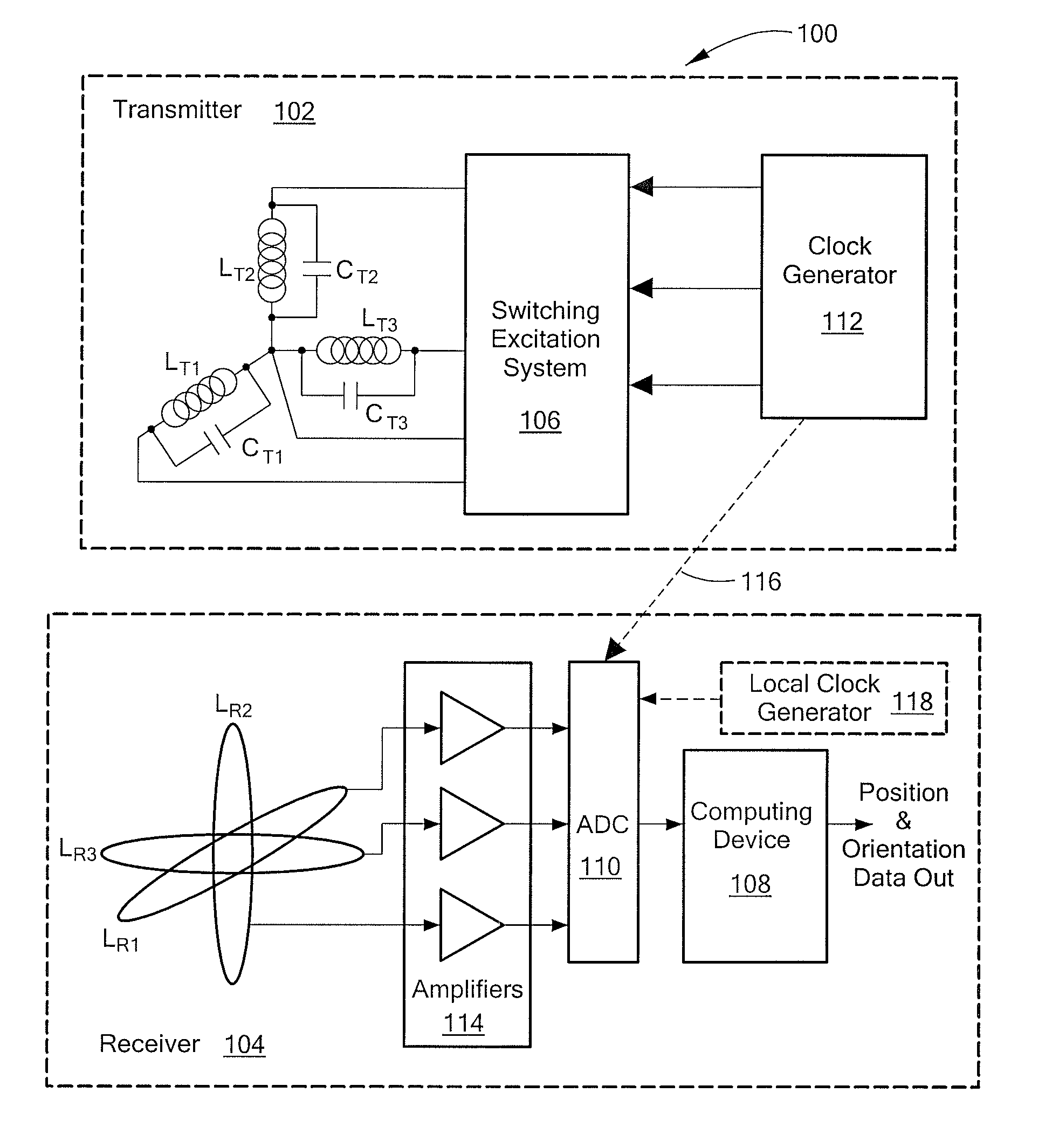
resonance. In accordance with this embodiment, the transmitter includes a plurality of resonant circuits, first and second sets of digitally controllable switches, first and second sets of pulse generators, sense circuitry, and a controller. Each resonant circuit has a
transmitter coil, a resonating
capacitor electrically coupled in parallel with the
transmitter coil, and a tuning
capacitor connected by a corresponding second digitally controllable switch in parallel with the resonating
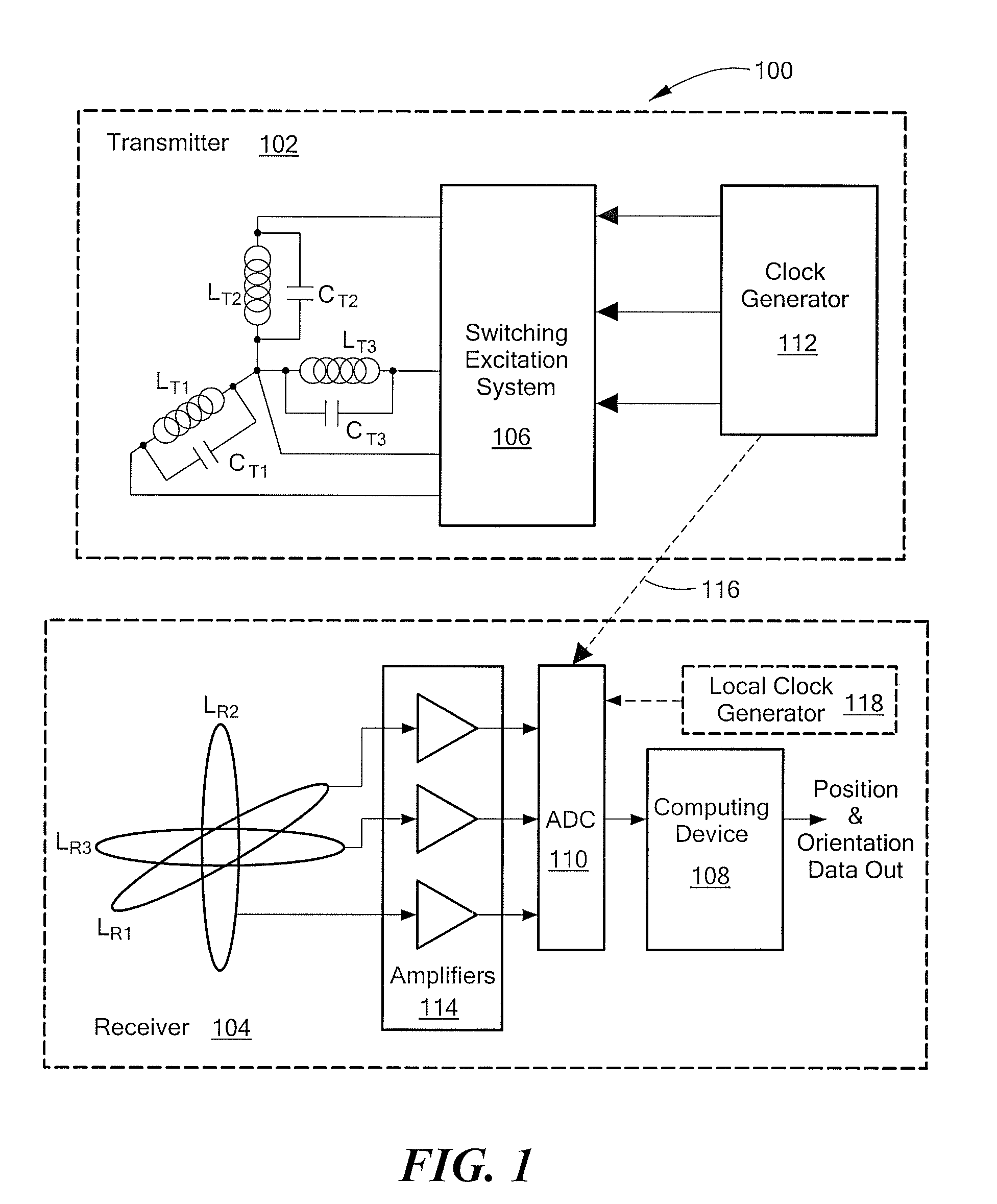
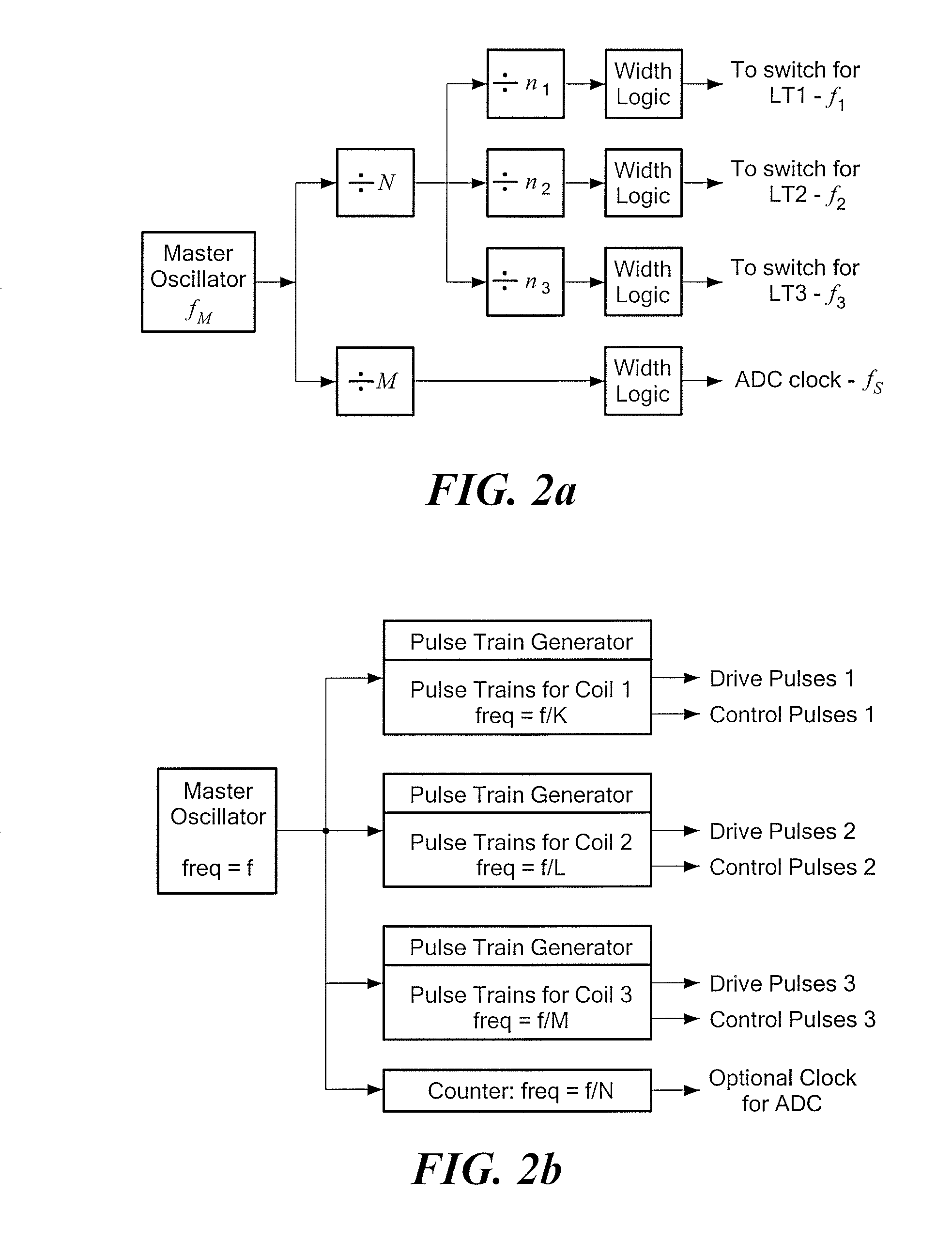
capacitor. Each of the first set of digitally controllable switches is electrically coupled in series between one end of one of the resonant circuits and one terminal of a power source. Each of the other ends of the resonant circuits is electrically coupled to the other terminal of the power source. Each of the first set of pulse generators generates periodic digital pulses for controlling one of the first set of digitally controllable switches, thereby sustaining continuous, periodic, and substantially sinusoidal currents in the resonant circuits. In response to the respective continuous, periodic, and substantially sinusoidal currents, the transmitter coils generate electromagnetic fields defining a reference coordinate system for the magnetic
tracking system. Each of the second set of digitally controllable switches is electrically coupled in series between one end of one of the tuning capacitors and the other terminal of the power source. The other end of each tuning capacitor is attached to its corresponding resonant circuit at the same end as the first digitally controllable switch. Each of the second set of pulse generators generates digital pulses for controlling one of the second set of digitally controllable switches, thereby switchably
coupling the respective tuning capacitors in parallel with the respective resonating capacitors. The sense circuitry measures the currents sustained in the resonant circuits, and the controller controls the timing of the digital pulses generated by the second set of pulse generators based on the current measurements of the sense circuitry, thereby controlling operation of the second set of digitally controllable switches for reducing the
power consumption of the resonant circuits. Tuning for minimum power also compensates for changes in transmitter
operating frequency should that be necessary to avoid interference between independent transmitters operating near each other.
[0019]In yet another embodiment, the presently disclosed magnetic
tracking system is configured so that the transmitter can fit inside a thin flat box, thereby facilitating embedding the transmitter box into the user's environment, and increasing the likelihood that the transmitter box would be viewed by the user as a feature of, rather than an obstacle in, that environment. In accordance with this embodiment, the magnetic
tracking system includes a coil
assembly having a generally flat transmitter housing with a top surface generally defining a top surface plane, and a plurality of transmitter coils fixedly positioned within the transmitter housing. Each of the transmitter coils has a center and coil turns that generally lie in a plane substantially parallel to the top surface plane. In addition, the center of each
transmitter coil is displaced from the centers of the other transmitter coils.

