
Method and system for controlling propulsion systems

Inactive Publication Date: 2010-10-28
GENERAL ELECTRIC CO
View PDF16 Cites 37 Cited by
  • Summary
  • Abstract
  • Description
  • Claims
  • Application Information

AI Technical Summary

Benefits of technology

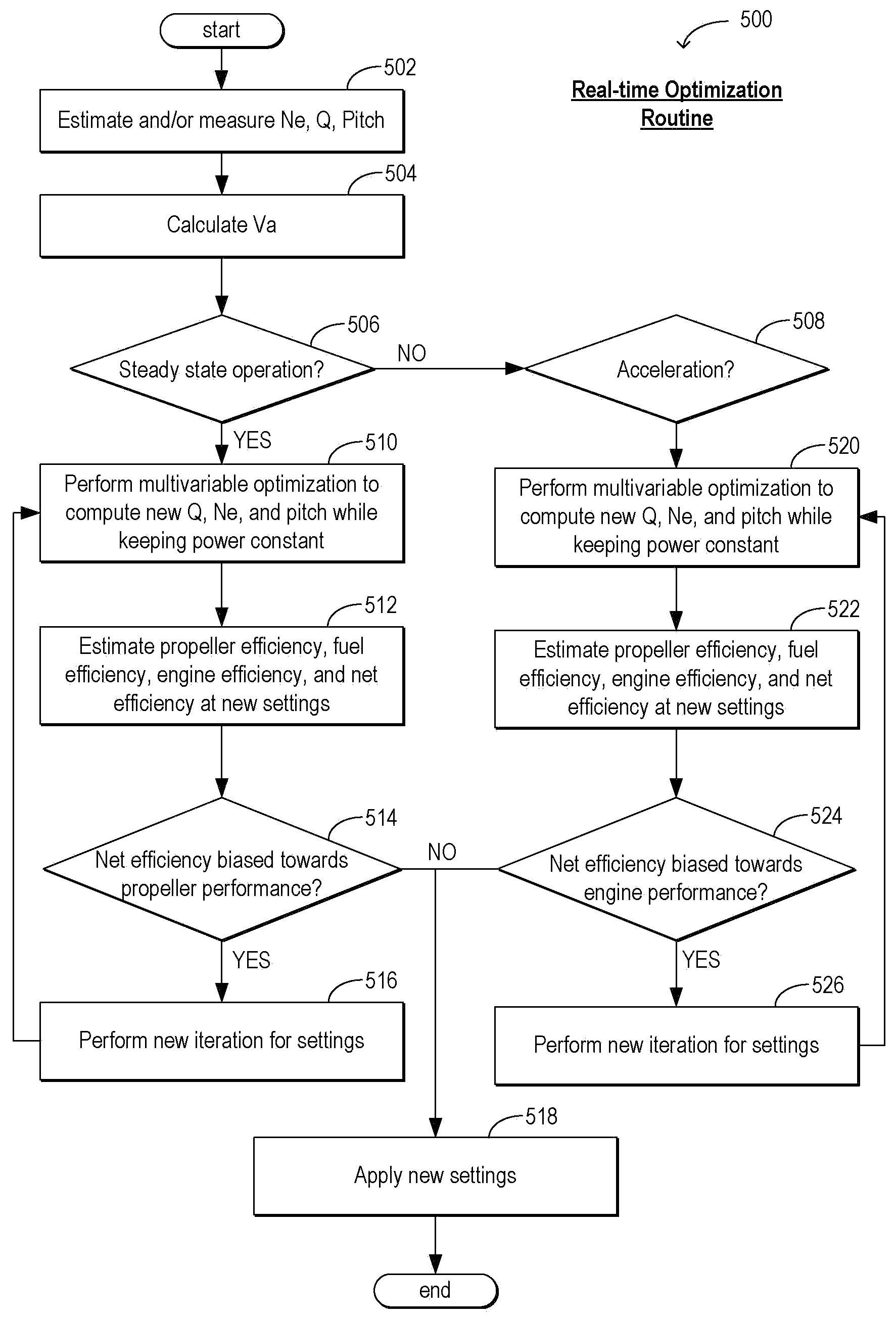
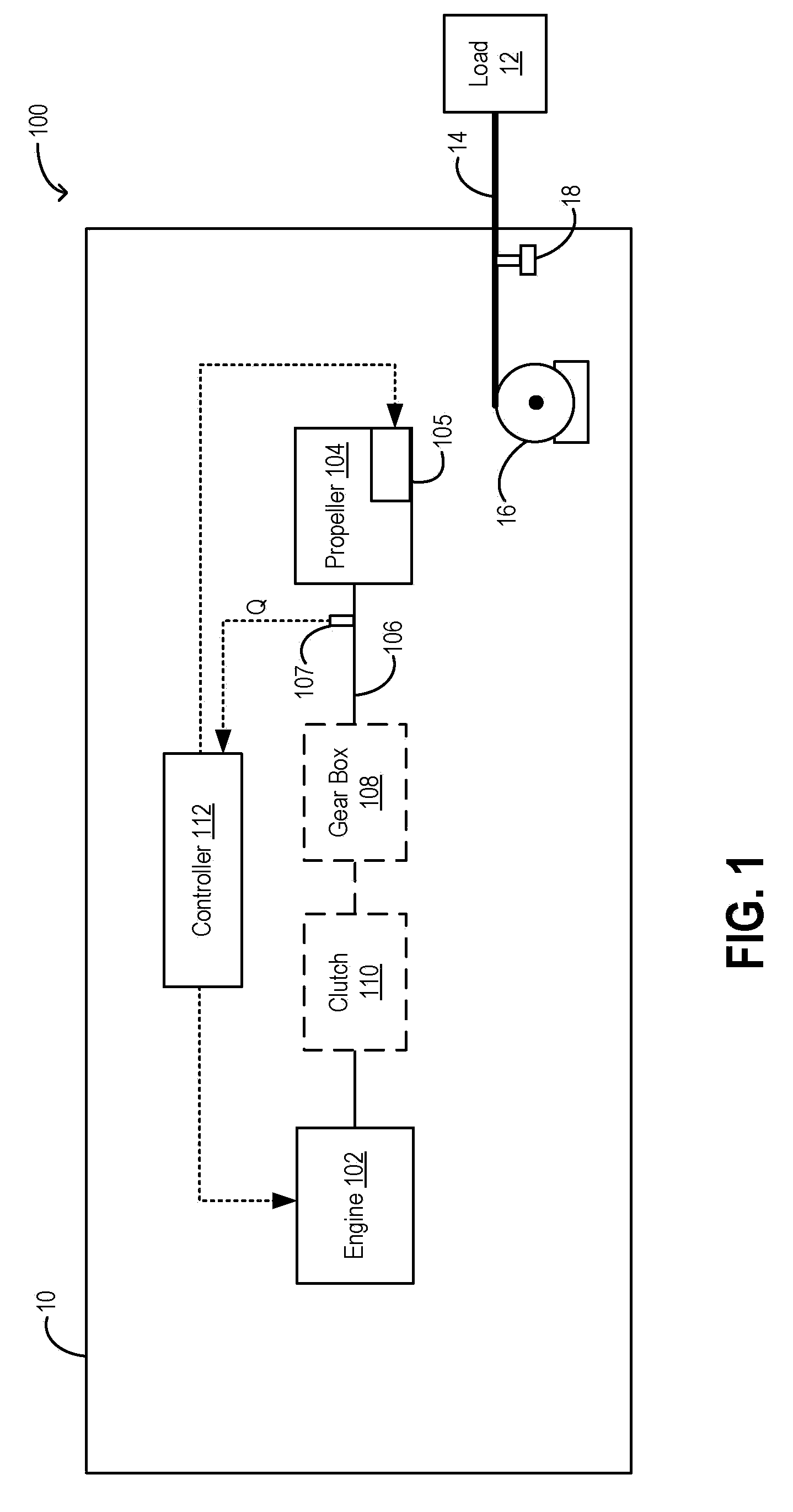
[0006]In one example, a propulsion system is configured with a controllable pitch propeller. In response to an operator power request, vessel operating data are estimated in real-time. The estimated data includes an estimate of the prevalent propeller torque (for example, using a torsion meter, or sensor, mounted on the propeller shaft, or inferred from the motor current of a propeller's pitch controller), propeller pitch, engine speed, and other vessel operating conditions (such as speed of advance in water). The estimated data is then used to update a propeller performance map (or performance curve), and an engine performance map (or performance curve). A multi-variable optimization routine based on the updated maps then enables propeller pitch and engine speed adjustments to be determined that can improve propeller efficiency and / or engine efficiency, or overall efficiency. As such, more than one adjustment to engine speed and / or propeller pitch may improve engine and / or propeller efficiency, or overall efficiency. A controller can select a propeller pitch and engine speed adjustment combination, from the range of adjustment possibilities, based on performance characteristics desired. In this way, propeller pitch and engine speed settings can be varied independently from one another. In one example, propeller pitch and engine speed are not set in a 1:1, fixed relationship. Consequently, adjustments to propeller pitch settings may not necessitate substantially equal and / or compensatory adjustments to engine speed settings, and vice versa. In one example, during acceleration, settings may be selected that enable enhanced engine performance, including an expedited response time and / or greater fuel savings. In another example, during a steady state mode of operation, settings may be selected that enable enhanced propeller performance.
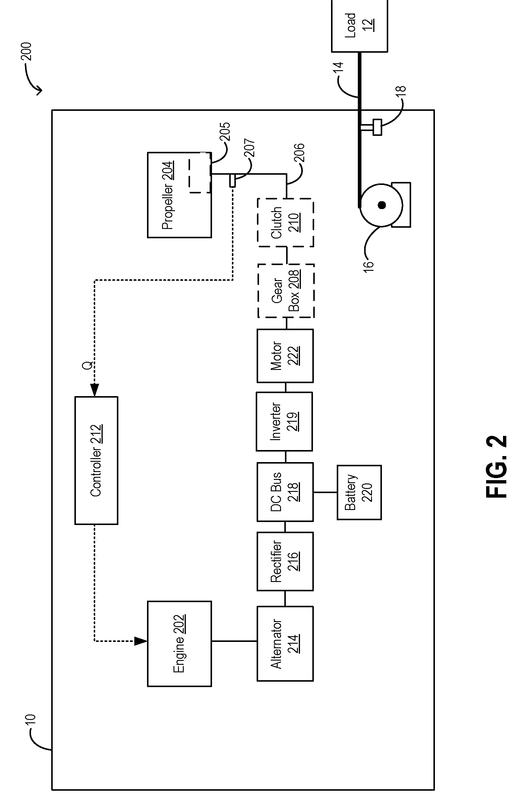
[0007]In another example, a propulsion system is configured with a fixed pitch propeller. Herein, a DC bus positioned intermediate the engine and the propeller enables engine performance to be decoupled from propeller performance, and allows the engine and propeller settings to be independently adjusted and optimized based on real-time vessel operating data. During steady state operation, in response to a power request, engine settings can be adjusted based on updated engine efficiency and fuel maps. Specifically, the multivariable optimization routine can select engine speed and torque settings that enable the requested power to be supplied most efficiently. During acceleration, engine settings can be adjusted to provide greater fuel savings. Propeller settings, such as propeller speed, may then be adjusted based on engine settings.
[0009]In this way, engine and propeller settings may be adaptively and independently reconfigured, based on the speed and / or power requested, and further based on real-time vessel operating data, to thereby enable both engine and propeller performances to be independently optimized. By further biasing the adjustments to engine and / or propeller settings responsive to a vessel mode of operation and / or selected vessel performance characteristics, engine and propeller performances may be improved.
[0011]The hybrid drive system may enable engine and propeller performances to be decoupled, for example, by decoupling engine and propeller loads, so that the engine and propeller performances may be independently adjusted and optimized. For example, the engine torque may be adjusted by receiving power from a battery during loaded operations, and then charging the battery during lighter loads. Also, the hybrid drive system may be adjusted to meet transient load changes with stored electrical energy and / or to reconfigure power distribution between auxiliary and propulsion circuits responsive to changes in power demand as well as engine and / or propeller operating conditions (such as during engine and / or propeller degradation). In doing so, a flexible and reconfigurable system may be provided that increases system reliability.

Problems solved by technology

Consequently, adjustments to propeller pitch settings may not necessitate substantially equal and / or compensatory adjustments to engine speed settings, and vice versa.

Method used


Image

  • Method and system for controlling propulsion systems
  • Method and system for controlling propulsion systems
  • Method and system for controlling propulsion systems

Examples


Embodiment Construction

[0020]Marine propulsion systems, such as those depicted in FIGS. 1-3D, in vessels such as tugboats, are controlled by propulsion control programs. Based on real-time knowledge of vessel operating conditions (such as propeller torque, engine speed, speed of advance in water, etc.), engine and propeller settings can be independently and dynamically adjusted to enable engine and propeller performances to be better matched. As such, differing variables affect engine and propeller performances in substantially different ways. Thus, by performing a multivariable optimization routine, such as those depicted in FIGS. 4-5, wherein both engine and propeller settings are independently reconfigured in response to real-time vessel operating data, the performances of both the engine and the propeller of a vessel propulsion system are improved, thereby enhancing the overall efficiency of the propulsion system. Furthermore, by performing a reconfiguration routine, such as depicted in FIG. 6, wherei...


PUM


Abstract

Methods and systems are provided for controlling a propulsion system of a vessel including an engine and a propeller. In one embodiment, the method comprises independently adjusting each of an engine setting and a propeller setting responsive to real-time vessel operating data.

Description

FIELD[0001]The subject matter disclosed herein relates to methods and systems for controlling propulsion systems, such as marine propulsion systems.BACKGROUND[0002]Marine propulsion systems, such as those on tugboats, enable a vessel to be easily and rapidly maneuvered in response to sudden and widely varying changes in load, direction, speed, etc. In some examples, propulsion control can be provided by adjusting propeller pitch and torque in a predetermined relationship based on a requested engine speed.[0003]However, propeller performance and engine performance are largely dictated for a given propeller design by variables including propeller pitch, rotational speed, and speed of advance in water. Variables such as speed of advance in water are, in turn, variably dependent on external influences such as wind load, sea load, towing load, and the like. The inventors herein have recognized that the high degree of variability of these loads can thus make it difficult for propulsion co...

Claims


Application Information

Patent Timeline
IPC IPC(8): G05D1/00B63H21/21B63H23/32
CPCF02D29/02B63H3/10
Inventor VEIT, FRANK WILLIAMDAIGLE, JEFFREY LOUIS
Owner GENERAL ELECTRIC CO
Learn More