Driving-force transmitting apparatus for four-wheel-drive vehicle

a transmission apparatus and four-wheel drive technology, applied in the direction of mechanical control devices, instruments, manual control with single controlling member, etc., can solve the problems of deteriorating fuel efficiency, disadvantageous deterioration of clutch-fastened responsiveness, and seized multi-plate clutch mechanism, so as to prevent deterioration of fuel efficiency and fuel efficiency. , the effect of no friction loss

Inactive Publication Date: 2010-10-28
UNIVANCE CORP
View PDF6 Cites 50 Cited by
  • Summary
  • Abstract
  • Description
  • Claims
  • Application Information

AI Technical Summary

Benefits of technology

[0076]According to the present invention, since the rear-wheel drive system becomes in a full stop state in the two-wheel drive mode, no friction loss occurs. Therefore, deterioration in fuel efficiency can be prevented, and fuel efficiency when use in the two-wheel drive mode despite a four-wheel-drive vehicle can be at the same level of fuel efficiency of a two-wheel-drive vehicle.
[0077]Also, when switching is made from the four-wheel drive mode to the two-wheel drive mode, after the fastening of the second disengaging mechanism provided between the rear-wheel differential device and the rear-wheel driving shaft is released, a disconnecting operation of the first disengaging mechanism provided on a side of the first driving-force transmitting direction converting unit, which transmits the driving force of the engine to the rear wheels while changing its rotating direction, is performed, thereby eliminating the driving force by the rotation of the rear wheels. With this, the torque acting on the

Problems solved by technology

However, in driving-force distribution control, the multi-plate clutch mechanism may be seized up unless sufficient lubrication is provided.
However, clutch-fastened responsiveness is disadvantageously deteriorated.
However, the above-described driving-force transmitting apparatus provided to an FF-vehicle-base four-wheel-drive vehicle has the following problems.
However, with the rotation of the right-rear wheel 324 and the left-rear wheel 322, a transmission route for transmitting the driving force to the rear wheels including the rear-wheel propeller shaft 314 and the rear-wheel differential device 326 always rotates to cause friction loss due to agitation of oil and friction of a bearing portion, and other factors, thereby disadvantageously deteriorating fuel efficiency.
In this case, if the coupling sleeve is presse

Method used


Image

  • Driving-force transmitting apparatus for four-wheel-drive vehicle
  • Driving-force transmitting apparatus for four-wheel-drive vehicle
  • Driving-force transmitting apparatus for four-wheel-drive vehicle

Examples


Embodiment Construction

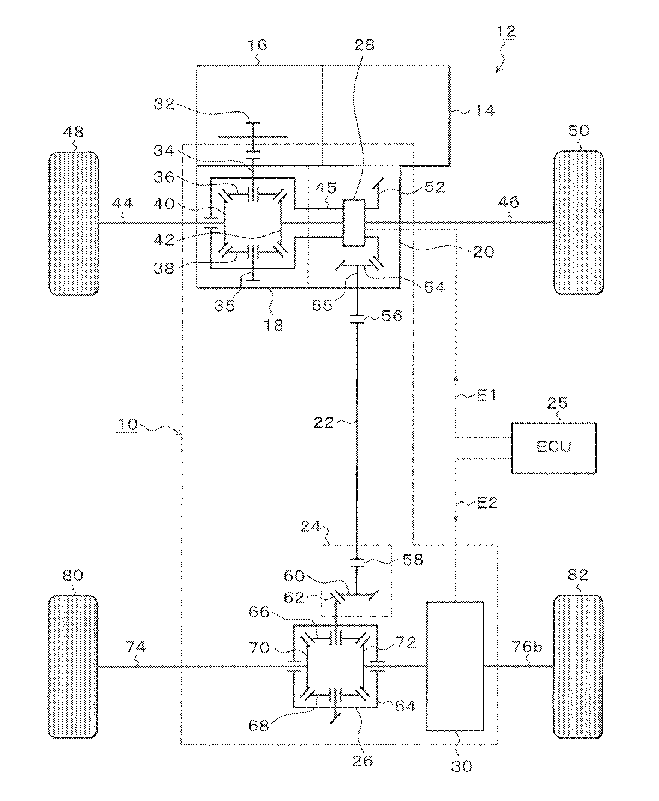
[0107]FIG. 4 is an illustrative diagram depicting, with a skeleton diagram, an embodiment of a driving-force transmitting apparatus for a four-wheel-drive vehicle according to the present invention. In FIG. 4, a driving-force transmitting apparatus 10 of the present invention is mounted on an on-demand-type full-time four-wheel-drive vehicle 12, and includes a front-wheel differential device 18, a first driving-force transmitting direction converting unit 20, a propeller shaft 22, a second driving-force transmitting direction converting unit 24, and a rear-wheel differential device 26. Furthermore, a disengaging device 28 is provided between the front-wheel differential device 18 and the first driving-force transmitting direction converting unit 20, and a multi-plate clutch mechanism 30 functioning as a driving-force distributing device is provided between the rear-wheel differential device 26 and, for example, a right-rear wheel 82, that is, rear-wheel driving shafts 76a and 76b th...


PUM


Abstract

A transmitting apparatus includes a disengaging device that disengages a driving force from a front-wheel differential device to a first driving-force transmitting direction converting unit 20 and a multi-plate clutch mechanism provided between an output of a rear-wheel differential device and a right-rear wheel and capable of successively adjusting a fastening force. Drag torque when the fastening of the multi-plate clutch mechanism is released is set smaller than friction torque of a rear-wheel drive system between the first driving-force transmitting direction converting unit and a second driving-force transmitting direction converting unit. A controller unconnects the disengaging device and releases the fastening of multi-plate clutch mechanism when switching to a two-wheel drive mode, thereby stopping the rotation of the rear-wheel drive system.

Description

[0001]This application is a priority based on prior application No. JP 2009-104752, filed Apr. 23, 2009 and No. JP 209-110578, filed Apr. 30, 2009, in Japan.BACKGROUND OF THE INVENTION[0002]1. Field of the Invention[0003]The present invention relates to driving-force transmitting apparatuses for four-wheel-drive vehicles capable of switching between two-wheel drive and four-wheel drive and, in particular, a driving-force transmitting apparatus for a four-wheel-drive vehicle stopping the rotation of a portion not associated with transmission of a driving force in two-wheel drive.[0004]2. Description of the Related Arts[0005]In a conventional so-called on-demand-type full-time four-wheel-drive vehicle, as an example of a driving-force transmitting apparatus for a four-wheel-drive vehicle in which front wheels are driven in two-wheel drive and distribution of a driving force to rear wheels is controlled by a driving-force distributing device in four-wheel drive, an apparatus shown in F...

Claims


Application Information

Patent Timeline
IPC IPC(8): G06F19/00F16D13/74F16H61/28F16D13/69
CPCY10T74/20073B60K23/08F16D13/69
Inventor KONDO, HIROYUKIMASUDA, YOSUKEYOKOTA, KENGONOYORI, HEDETOYANO, NORIATSU
Owner UNIVANCE CORP
Why Eureka
Try Eureka