Signal processor and error correction process

Inactive Publication Date: 2010-10-28
SONY CORP
View PDF8 Cites 10 Cited by
  • Summary
  • Abstract
  • Description
  • Claims
  • Application Information

AI Technical Summary

Benefits of technology

[0009]The transmission system has been developed to employ a wired transmission path of relatively high transmission quality. Thus, with the transmission system described above, the number of transmission error bits for each frame or each block, when one frame is divided into a plurality of blocks, is significantly small. The transmission errors occur at a ratio of about one bit for each frame or each block in transmission of control signals and sensor signals. Such transmission errors may preferably be corrected. Convolutional codes may be adapted in an error correction process to provide highly efficient error correction. Convolutional code-based error correction is, however, too large-scale for error correction of transmission data in a transmission path of relatively high transmission quality. In addition, such an error correction process may increase a circuit size.
[0010]It is therefore desirable to provide a novel and improved signal processor and an error correction process which can correct errors of data transmitted via a transmission path of relatively high transmission quality using a relatively small-scales circuit configuration.
[0011]An embodiment of the invention is a signal processor, which includes: a signal receiving section for receiving signals encoded under a predetermined code rule; a rule violation detecting section for detecting code rule violation included in the signals received by the signal receiving section; an error range specifying section for specifying a range in which an error bit is included out of a bit string which constitutes the signals on the basis of a position of the code rule violation detected by the rule violation detecting section; and an error correcting section for correcting one error bit in the range specified by the error range specifying section so that the code rule violation detected by the rule violation detecting section is eliminated.
[0012]The error correcting section may include: a correction value determination section for determining a value of a correction bit which can eliminate the code rule violation detected by the rule violation detecting section for each bit in the range specified by the error range specifying section; an amplitude difference calculating section for calculating difference between an amplitude value of the signals corresponding to a value of the correction bit determined by the correction value determination section and an amplitude value of the signals corresponding to a previous bit of the correction bit; a maximum difference selecting section for comparing difference in the amplitude values corresponding to each of the bits in the range calculated by the amplitude difference calculating section and selecting a value of a correction bit with the maximum difference in the amplitude value; and a correction processing section for correcting an error using a value of the correction bit selected by the maximum difference selecting section.
[0023]Another embodiment of the invention is an error correction process, which may include the steps of: receiving signals encoded under a predetermined code rule; detecting code rule violation included in the signals received in the step of receiving signals; specifying a range in which an error bit is included out of a bit string which constitutes the signals on the basis of a position of code rule violation detected in the step of detecting rule violation; and correcting one error bit in the range specified in the step of specifying a range so that code rule violation detected in the step of detecting code rule violation is eliminated.

Problems solved by technology

It is therefore difficult to transmit the NRZ coded signals together with DC components, such as power supply.
Such a PLL circuit provided at the receiver side may increase electric current to be consumed.
Such a transmission system operates at a high clock rate and thus consumes a significantly increased amount of electric current.
Convolutional code-based error correction is, however, too large-scale for error correction of transmission data in a transmission path of relatively high transmission quality.
In addition, such an error correction process may increase a circuit size.

Method used


Image

  • Signal processor and error correction process
  • Signal processor and error correction process
  • Signal processor and error correction process

Examples


embodiment

1. Embodiment

[0040]Now, an embodiment of the invention will be described. The present embodiment relates to a technique of efficiently correcting errors in data transmitted via a transmission path of relatively high transmission quality. The transmission path of relatively high transmission quality herein has, for example, a bit error rate (BER) of not higher than about 10−6. With such a transmission path, transmission errors can be sufficiently eliminated by correcting about one error bit in each frame or each block. The present embodiment therefore provides an error correction process to efficiently detect one error bit in each frame or each block on the basis of code rule violation included in received data and to correct that error bit efficiently.

1-1. Configuration of Information Processing Device 10

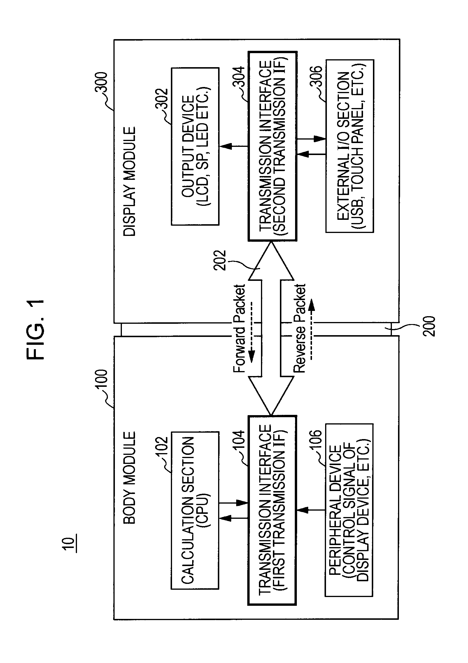
[0041]With reference to FIG. 1, a configuration of an information processing device 10 according to the present embodiment will be described briefly. FIG. 1 illustrates an exemplary...


PUM


Abstract

A signal processor, which includes: a signal receiving section for receiving signals encoded under a predetermined code rule; a rule violation detecting section for detecting code rule violation included in the signals received by the signal receiving section; an error range specifying section for specifying a range in which an error bit is included out of a bit string which constitutes the signals on the basis of a position of the code rule violation detected by the rule violation detecting section; and an error correcting section for correcting one error bit in the range specified by the error range specifying section so that the code rule violation detected by the rule violation detecting section is eliminated.

Description

BACKGROUND OF THE INVENTION[0001]1. Field of the Invention[0002]The present invention relates to a signal processor and an error correction process.[0003]2. Description of the Related Art[0004]Portable devices, such as mobile phones, have a user operation section and an information display section which are connected with a connecting section. The connecting section is often constituted by a movable member. Typical examples of such a movable member include a flip structure of a flip mobile phone. The recent mobile phones provide video viewing and image-capturing capabilities as well as calling and message services. The connecting section should move in a complex manner to satisfy user demands. For example, when viewing video on his / her movable phone, a user may wish to turn the display section to himself / herself and retract the operation section unnecessary to video viewing. It is therefore necessary to provide a structure of the connecting section to easily change angles and positi...

Claims


Application Information

Patent Timeline
IPC IPC(8): H03M13/05G06F11/10H04M1/72403
CPCH04L25/4917
Inventor OGISO, TAKAYUKI
Owner SONY CORP
Why Eureka
Try Eureka