
Flexible electrical cable

a flexible, electrical cable technology, applied in the direction of flexible conductors, power cables, conductors, etc., can solve the problems of particularly resistant to tensile forces and its use restriction to relatively low data rates

Inactive Publication Date: 2010-11-04
GROGL FERDINAND +1
View PDF5 Cites 18 Cited by
  • Summary
  • Abstract
  • Description
  • Claims
  • Application Information

AI Technical Summary

Benefits of technology

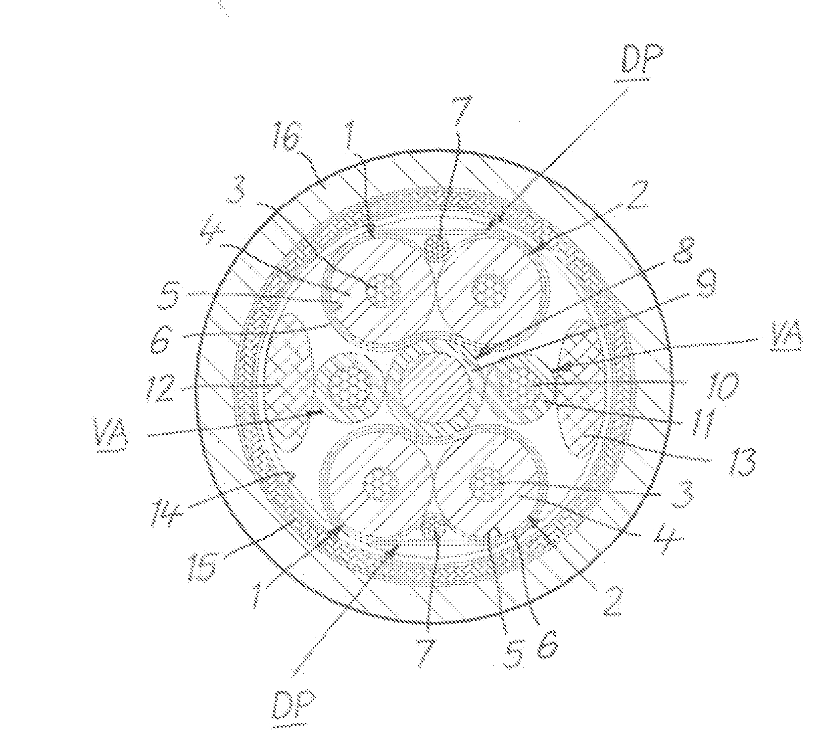
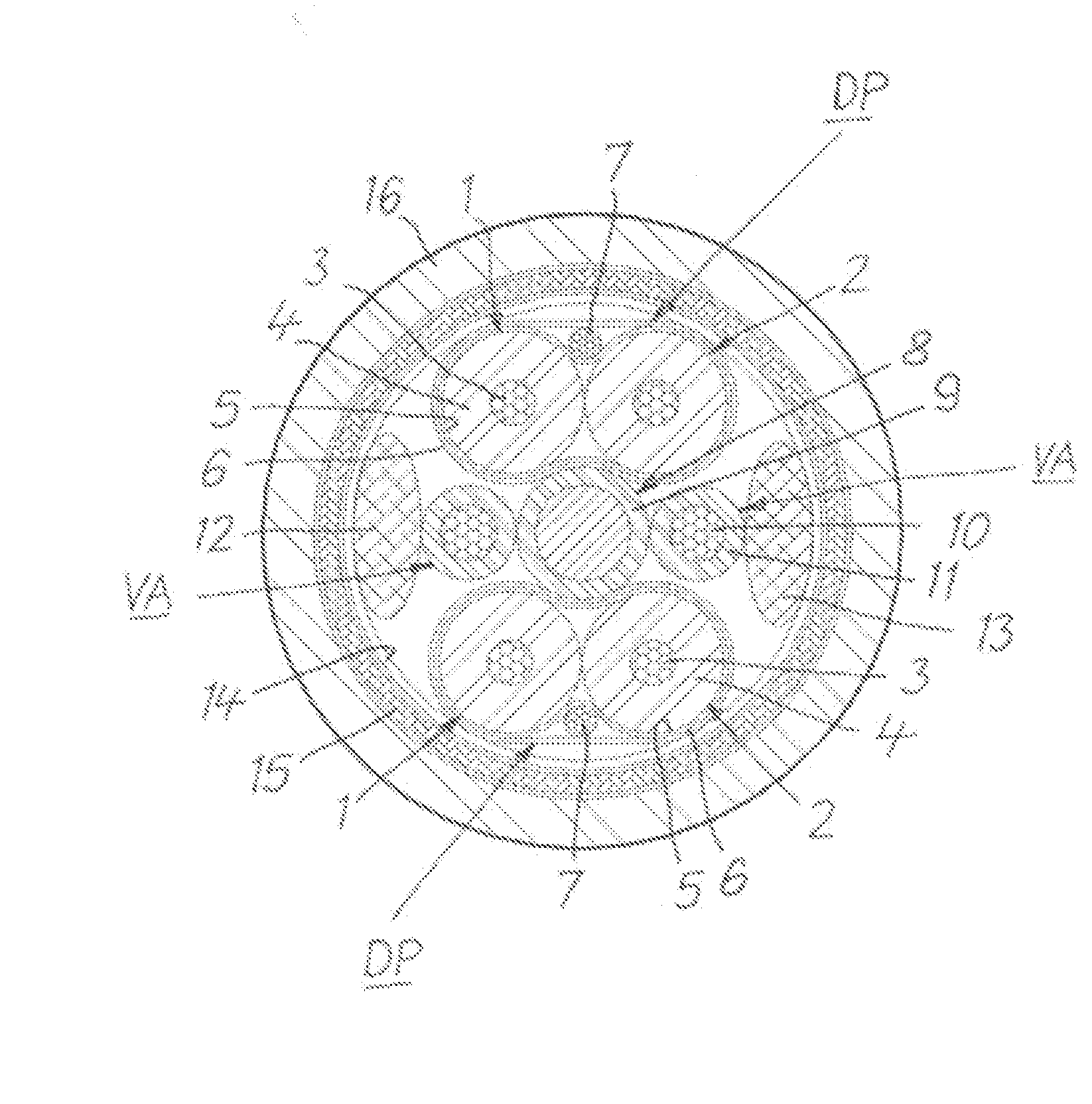
[0012]This cable can be produced with conventional technology using fundamentally known simply constructed machines and associated fixtures. Because of the central spine, it has outstanding mechanical characteristics, in particular a tensile strength which is necessary for many applications. As the spine, which is resistant to tensile forces, is easily bendable and the other elements of the cable are twisted around said spine, the overall cable is easily bendable. The data pairs are in each case surrounded by a screen which screens the respective transmission circuits very well against interference radiated from outside, namely also for very high frequencies or data rates. This screening, which is effective for frequencies of 1.2 GHz for example, is achieved by the interaction of the metal foil which is closed on all sides and the metallized synthetic fleece which is likewise an almost closed metallic sleeve with a covering>85% for the data pairs. The screening so formed also prevents interference being radiated from the data pairs which could mutually interact or which could also be effective outside the cable. A further advantage of this cable is that there are no run-time differences in the data transmission on the data pairs, as the data cores run parallel to one another and are therefore of equal length.

Problems solved by technology

However, it is not particularly resistant to tensile forces and its use is restricted to relatively low data rates.

Method used


Image

  • Flexible electrical cable
  • Flexible electrical cable

Examples


Embodiment Construction

:

[0015]The cable shown in cross section in the drawing has two data pairs DP in each of which two data cores 1 and 2 are arranged running parallel to one another. Each data core 1 and 2 respectively has a conductor 3 preferably made of copper which is surrounded by an insulation 4. The conductor 3 can be a solid wire or with advantage a stranded conductor. It can have an external layer of tin, silver or nickel. The conductor 3 can also consist of a cadmium-free copper alloy. With advantage, the insulation 4 consists of expanded insulating material such as polyethylene or polypropylene for example. An insulating material suitable for high temperatures can also be used such as polytetrafluoroethylene (PTFE), fluoroethylenepropylene (FEP) or polyfluoroalkene (PFA) for example. An expanded insulation 4 can be provided with a smooth outer skin in known “skin” technology. With advantage, the insulation 4 consists of a low-density PTFE and, if necessary, of a sintered “skin” layer of PTFE ...


PUM

PropertyMeasurementUnit
frequencyaaaaaaaaaa
frequenciesaaaaaaaaaa
thicknessaaaaaaaaaa

Abstract

A flexible electrical cable having a centre part surrounded by a sheath (16) made of insulating material is specified in which are arranged at least one data pair (DP) consisting of two data cores (1, 2) which are used for data transmission and are surrounded by a common screen containing a metallized synthetic fleece, and at least one supply core (VA) which is used for supplying power, which are surrounded by a common electrical screen (15). In the centre part, at least two screened data pairs (DP) with data cores (1, 2) running parallel to one another are arranged separately from one another, the screen of which has a synthetic-material-clad metal foil (5) surrounding said screen on all sides, the metal side of which faces outwards, over which the metallized synthetic fleece (6) is arranged in contact with the metal side. At least one supply core (VA) is present in the centre part, and data pairs (DP) and supply cores (VA) are twisted around a central spine (8) which is resistant to tensile forces and is easily bendable, the supply core (VA) being arranged between the data pairs (DP).

Description

RELATED APPLICATION [0001]This application claims the benefit of priority from Eu No. 08291053.0, filed on Nov. 12, 2008, the entirety of which is incorportaed by reference.BACKGROUND [0002]1. Field of the Invention[0003]The invention relates to a flexible electrical cable having a centre part surrounded by a sheath made of insulating material in which are arranged at least one data pair consisting of two data cores which are used for data transmission and are surrounded by a common screen containing a metallized synthetic fleece, and at least one supply core which is used for supplying power, which are surrounded by a common electrical screen over which the sheath is arranged, the data cores and the supply core each having an electrical conductor which is surrounded by an insulator (EP 1 589 541 B1).[0004]2. Description of Related Art[0005]Cables of this kind are used, for example, in automobile engineering in so-called driver assistance systems. They must be capable of being mecha...

Claims


Application Information

Patent Timeline
Patent Type & Authority Applications(United States)
IPC IPC(8): H01B9/02
CPCH01B11/00H01B9/003H01B7/04
Inventor GROGL, FERDINANDPOPP, HARRY
Owner GROGL FERDINAND
Learn More