1d gesture light control

a gesture light and control technology, applied in the field of lighting systems, can solve the problems of not being able to react to the movement of objects, not using time-of-flight measurements of ultrasonic signals, etc., and achieve the effect of reducing the influence of acoustic pressure on users

Inactive Publication Date: 2010-11-04
LITE ON TECH CORP
View PDF7 Cites 21 Cited by
  • Summary
  • Abstract
  • Description
  • Claims
  • Application Information

AI Technical Summary

Benefits of technology

[0007]The ultrasonic transmitter may for instance emit sound at a frequency of 40 kHz. Although alternatives to the use of ultrasonic transmitters / receivers, such as for instance infrared or radar transmitters / receivers would be capable of measuring the time-of-flight of the respective signals, ultrasound is in particular suitable for the present application, since the time-of-flight (where the typical distance is between 0.2 and 2 meter) can be measured in milliseconds rather than in nanoseconds, which allows for easy and accurate measurement with low cost processing equipment. The system of the invention can be produced at very low cost, since piezoelectric acoustic transducers are very cheap.
[0042]It is desirable that the ultrasound controlled lighting system is easy to produce in mass quantities, with low cost components, and has small dimensions so that it can be built-in in even in a small lamp.

Problems solved by technology

This system does however not use time-of-flight measurements of the ultrasonic signal, and thereby is not able to react to movement of the object.

Method used


Image

  • 1d gesture light control
  • 1d gesture light control
  • 1d gesture light control

Examples


Embodiment Construction

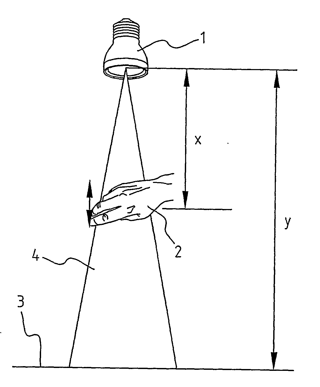
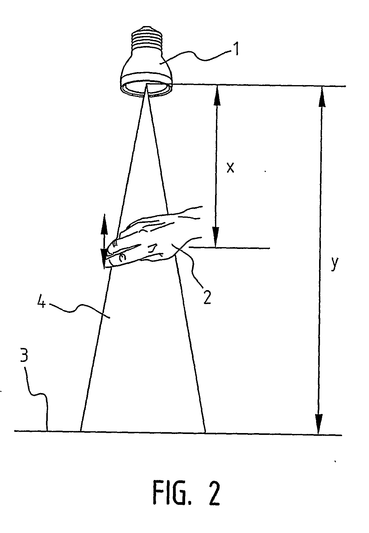
[0069]The lamp 1 as shown in FIG. 2 comprises a plurality of LEDs and an ultrasonic transceiver built-in in the centre of said plurality of LEDs. Also a processing means for translating the signals of the transceiver into control signals, and control means to adjust the light properties are built-in.

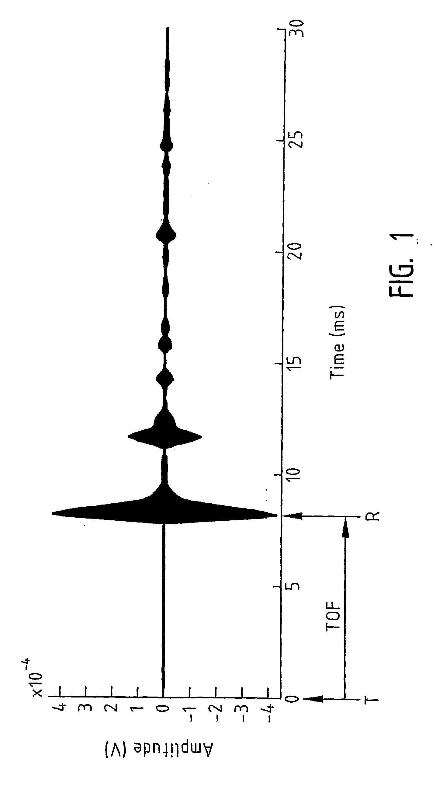
[0070]If the ultrasonic transceiver is switched on it will send an acoustic signal. If an object is present the acoustic signal will be reflected at the object and will be received by the ultrasonic transceiver inside the lamp. The time difference, called the time-of-flight, between sending and receiving the acoustic signal will be measured. If the distance between the object and the lamp 1 is changed another time-of-flight value will be measured. The detected movement of the object is a one-dimensional movement (the object must stay in the ultrasound beam cone). The change in time-of-flight will be translated into a change in a digital control signal. This control signal will control th...


PUM


Abstract

A lighting system comprising a lamp arranged to transform electricity into a light beam having properties such as intensity, colour, colour temperature, direction and beam cone angle, a light control means arranged to adjust said light beam properties, an ultrasonic transmitter arranged to transmit ultrasonic signals, an ultrasonic receiver arranged to receive reflected ultrasonic signals, and a processing means arranged to derive a time-of-flight signal representing the time differences between said transmitted and received ultrasonic signals and to send control signals to said light control means in dependence of said time-of-flight signal.

Description

FIELD OF THE INVENTION[0001]The invention relates to a lighting system comprising a lamp arranged to transform electricity into a light beam having properties such as intensity, colour, colour temperature, direction and beam cone angle, and a light control means arranged to adjust said light beam properties.BACKGROUND OF THE INVENTION[0002]Adjustment of a lamp's properties is well known to be achieved via a remote control (RC). A disadvantage of a remote control is the necessity of the presence of the remote control on the right location at a random moment. Also a lot of different remote controls are already present in the living room for TV, audio, VCR, CD / DVD player / recorder, etc. Further, the different buttons on a remote control can be confusing to the user. Finally, the costs of a remote control and the accompanying receiver are relatively high.[0003]Also control of electrical devices by the use of video cameras and movement detection software is known, wherein the user can con...

Claims


Application Information

Patent Timeline
Patent Type & Authority Applications(United States)
IPC IPC(8): H05B37/02G01J1/44H05B44/00
CPCG06F3/017H03K17/96H05B37/0227H03K2217/96007H05B33/0863H03K2217/94052H05B45/20H05B47/125Y02B20/40
Inventor VAN ENDERT, TONY PETRUS
Owner LITE ON TECH CORP
Why Eureka
Try Eureka