Monitoring a flexible power cable

Inactive Publication Date: 2010-11-04
ABB TECH AG
View PDF7 Cites 30 Cited by
  • Summary
  • Abstract
  • Description
  • Claims
  • Application Information

AI Technical Summary

Benefits of technology

[0012]The present invention proposes a system to monitor the actual bendings of the power cable to a floating offshore installation in real-time. This enables a monitoring unit to record the bendings of the power cable for evaluation. From this evaluation which can be software-based or expert based, the remaining useful life of the power cable can be estimated. Maintenance/repair operations can be planned and the risk for an outage (which is extremely

Problems solved by technology

The strain on the power cable arises from the bending o

Method used


Image

  • Monitoring a flexible power cable
  • Monitoring a flexible power cable
  • Monitoring a flexible power cable

Examples


Embodiment Construction

[0040]Detailed descriptions of the preferred embodiment are provided herein. It is to be understood, however, that the present invention may be embodied in various forms. Therefore, specific details disclosed herein are not to be interpreted as limiting, but rather as a basis for the claims and as a representative basis for teaching one skilled in the art to employ the present invention in virtually any appropriately detailed system, structure or manner.

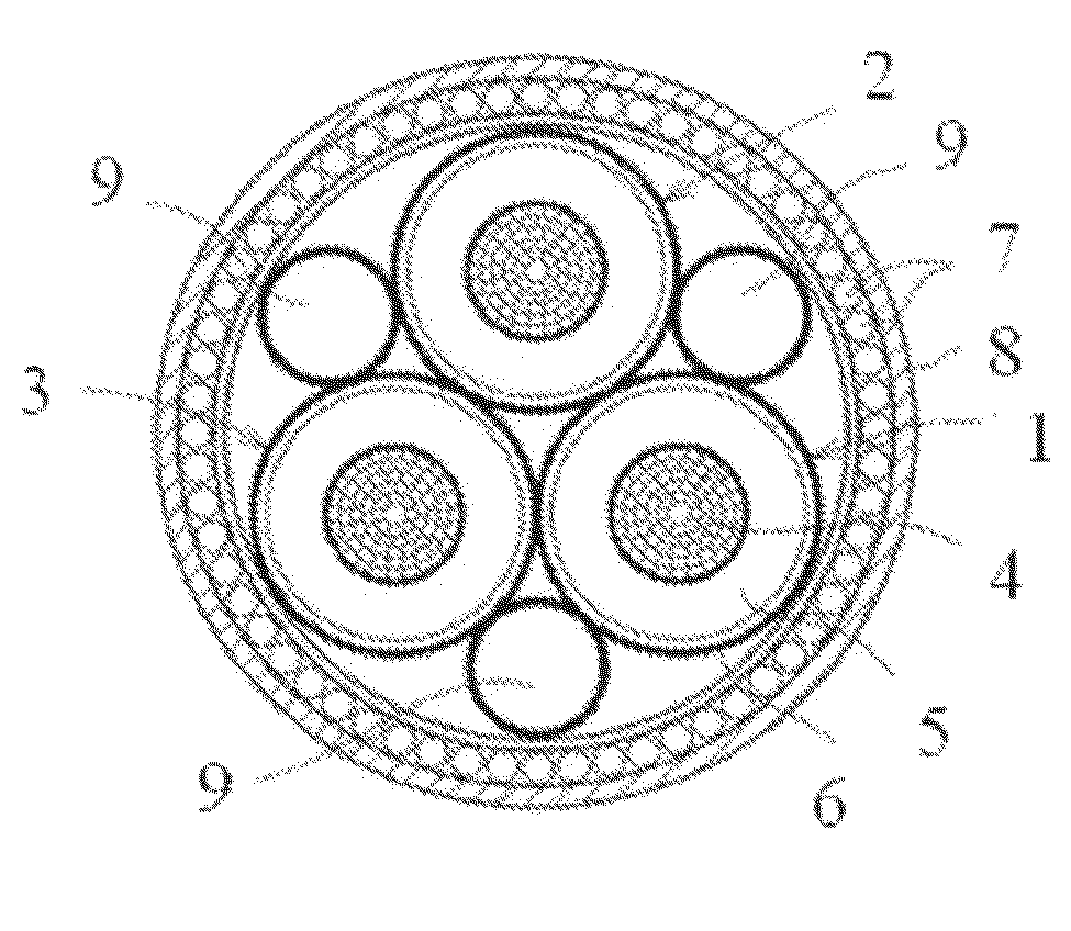
[0041]FIG. 1 shows a schematic diagram of a cross-section of a high voltage power cable on which the present invention could be used. A high voltage power cable can consist of one, two, three or more single-conductor cables. The power cable shown in FIG. 1 consists of three single-conductor cable cores 1-3. Each of the single-conductor cable cores having a metallic centre conductor 4 enclosed in an insulation layer 5 surrounded by a cable screen 6. The cable cores are provided with one or more common outer layers, such as armoring wi...


PUM


Abstract

An offshore monitoring system, for an electrical power cable connected between a fixed point and a movable point, or for an electrical power cable connecting two movable points. The system comprises at least one optical fiber acting as a continuously distributed strain measurement sensor attached to or arranged in said power cable, a device arranged for sending optical signals and a device arranged for receiving optical signals to determine the time variant bending of said power cable.

Description

TECHNICAL AREA[0001]The present invention relates to system for monitoring the bending and strain of a power cable connected to a moving offshore platform by measuring the strain in optical fibers attached to or incorporated into the power cable.TECHNICAL BACKGROUND[0002]Offshore installations such as oil / gas rigs, processing platforms, semi-submersible installations, etc, are more and more often connected with power cables to shore-based installations, fixed sub sea installations or another offshore installation. In case of floating rigs the power cables are subjected to repeated motions and bendings due to wave swell, wind pressure and / or tidal motions.[0003]To tolerate the motions of the floating offshore installation the power cables have to be somewhat flexible. The motions of the installation and the resulting bendings of the power cables however, can cause limitations for the useful life of the cable. The lifetime of a power cable is not only determined by the number of bendi...

Claims


Application Information

Patent Timeline
IPC IPC(8): G08B21/00G01N3/20
CPCG01M11/086G02B6/4417H01B7/32G01M11/085G01M5/0041G01M5/0091H01B9/005
Inventor WORZYK, THOMAS
Owner ABB TECH AG
Why Eureka
Try Eureka