Digital mapping system based on continuous scanning line of sight

a digital mapping and line of sight technology, applied in the field of mapping systems, can solve the problems inconvenient operation, and inability to meet the needs of users, and achieve the effect of reducing frame rate, reducing the number of frames, and reducing the cost of large format ccds

Active Publication Date: 2010-11-04
THE STATE OF ISRAEL MINIST OF AGRI & RURAL DEV AGRI RES ORG ARO VOLCANI CENT
View PDF32 Cites 52 Cited by
  • Summary
  • Abstract
  • Description
  • Claims
  • Application Information

AI Technical Summary

Benefits of technology

[0003]The subject invention concerns automated orthophoto, digital terrain model, digital surface model and camera model derivation from aerial photographs of a ground area. The subject in

Problems solved by technology

Prior art systems use expensive large format CCDs.
Prior art systems use

Method used


Image

  • Digital mapping system based on continuous scanning line of sight
  • Digital mapping system based on continuous scanning line of sight
  • Digital mapping system based on continuous scanning line of sight

Examples


Embodiment Construction

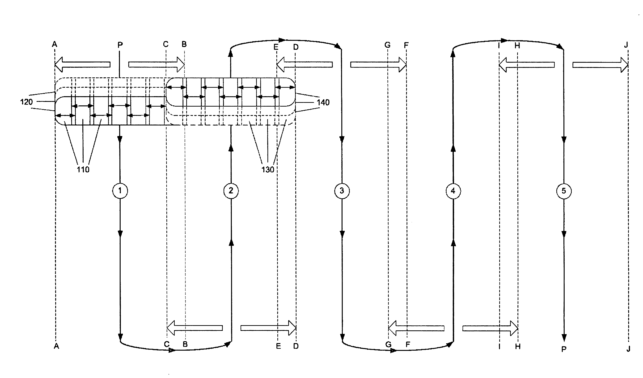
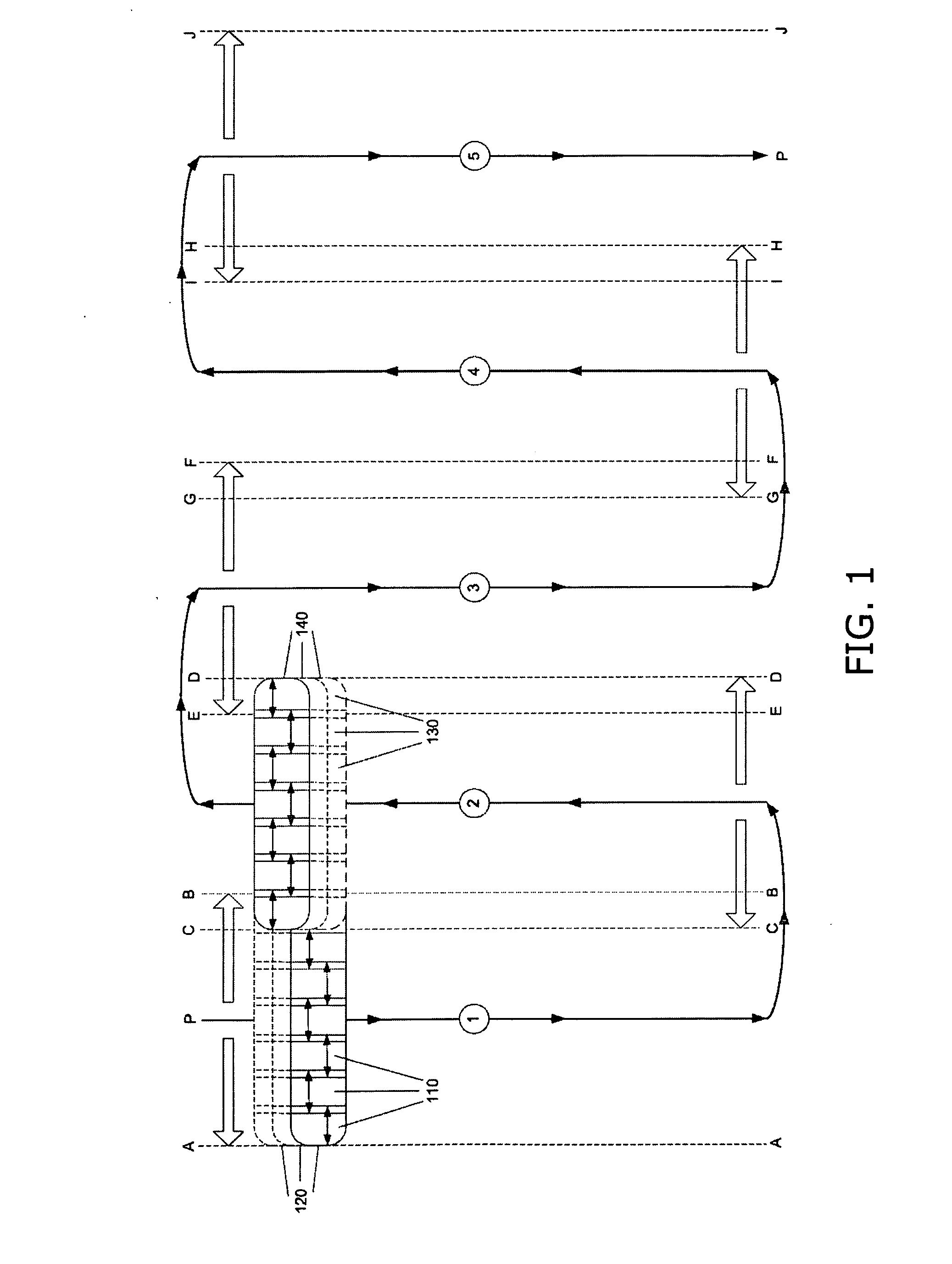
[0020]The subject invention concerns mapping, in particular generation of accurate terrain maps from a large number of aerial color photos captured by one or more CCD cameras mounted within a moving aircraft. The cameras' fields of view sweep back and forth, generally transverse to the direction of flight, so as to cover a wide strip of terrain surrounding the path of flight.

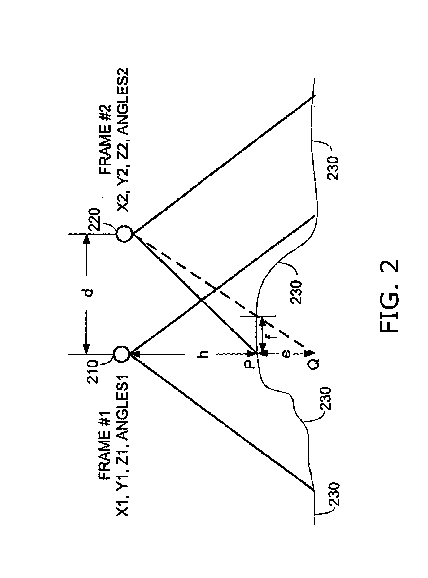
[0021]Conventional photogrammetry uses either a “frame” camera model or a “push-broom” camera model. Generally, a camera model solution is a function that maps each pixel (i, j) in an image captured by a camera into a ray defined by 6 degrees of freedom emanating from the camera. The classical 6 degrees of freedom comprise (x, y, z, kappa, phi, theta), where x, y and z are scalars, and kappa, phi and theta are angles. The camera model solution is generally obtained by sensing the camera's position and angles, or by using aerial triangulation using ground control points (GCPs). Obtaining a camera model is essenti...


PUM


Abstract

Apparatus for capturing images while in motion, including at least one CCD camera housed within an aircraft traveling along a flight path, for capturing aerial images of ground terrain, a motor for rotating an axis on which the at least one CCD camera is mounted, and for generating a sweeping back-and-forth motion for a field of view of the at least one CCD camera, the sweeping motion being transverse to the aircraft flight path, and an optical assembly connected to said at least one CCD camera.

Description

FIELD OF THE INVENTION[0001]The field of the subject invention is mapping systems. The subject invention relates to cartography, in particular to digital mapping systems.BACKGROUND OF THE INVENTION[0002]Airborne camera assemblies for capturing aerial photos are used for commercial and military cartography applications, including reconnaissance, mapping and terrain model generation. Conventional assemblies suffer from three drawbacks. (i) They are very expensive, because they use accurate wide-angle lens cameras with large format CCDs for replicating analog film cameras, inertial navigation units and motion stabilizers. (ii) They are very large and heavy, because they use large lenses. (iii) Due to short optical focal lengths, they require flight paths with low cruising altitudes. As a result, they have limited capability to cover large areas in short amounts of time.SUMMARY OF THE DESCRIPTION[0003]The subject invention concerns automated orthophoto, digital terrain model, digital su...

Claims


Application Information

Patent Timeline
IPC IPC(8): H04N7/18H04N5/335H04N13/221
CPCG02B26/0816G01C11/025G03B15/006H04N13/0221G02B27/644H04N5/23238H04N13/221H04N23/698H04N1/40H04N5/262
Inventor PECHATNIKOV, MICHAELZLOTNIK, VADIMKOSOY, VADIM
Owner THE STATE OF ISRAEL MINIST OF AGRI & RURAL DEV AGRI RES ORG ARO VOLCANI CENT
Why Eureka
Try Eureka