Vacuum insulator

a vacuum insulator and insulating material technology, applied in the direction of insulation for cooling apparatus, domestic cooling apparatus, lighting and heating apparatus, etc., can solve the problems of easy air infiltration, difficult to break down conventional buildings, and too thick thickness of insulating materials to build economic buildings, so as to improve vacuum maintenance performance and reduce air infiltration through adhesion parts of the envelope

Inactive Publication Date: 2010-11-04
KOREA ADVANCED INST OF SCI & TECH
View PDF0 Cites 19 Cited by
  • Summary
  • Abstract
  • Description
  • Claims
  • Application Information

AI Technical Summary

Benefits of technology

[0016]The present invention is conceived to solve the aforementioned problems. Accordingly, the present invention provides a vacuum insulator, in which air infiltration through an adhesion part of the envelope can be reduce

Problems solved by technology

However, in this idea, thickness of insulating materials is too thick to build economic buildings, and it inevitably requires breaking down conventional buildings.
However, the Low density polyethylene film LDPE 14a, 14b and the Linear low density polyethylene film LLDPE 15a, 15b have a problem of making air infiltration easy thr

Method used


Image

  • Vacuum insulator
  • Vacuum insulator
  • Vacuum insulator

Examples


first embodiment

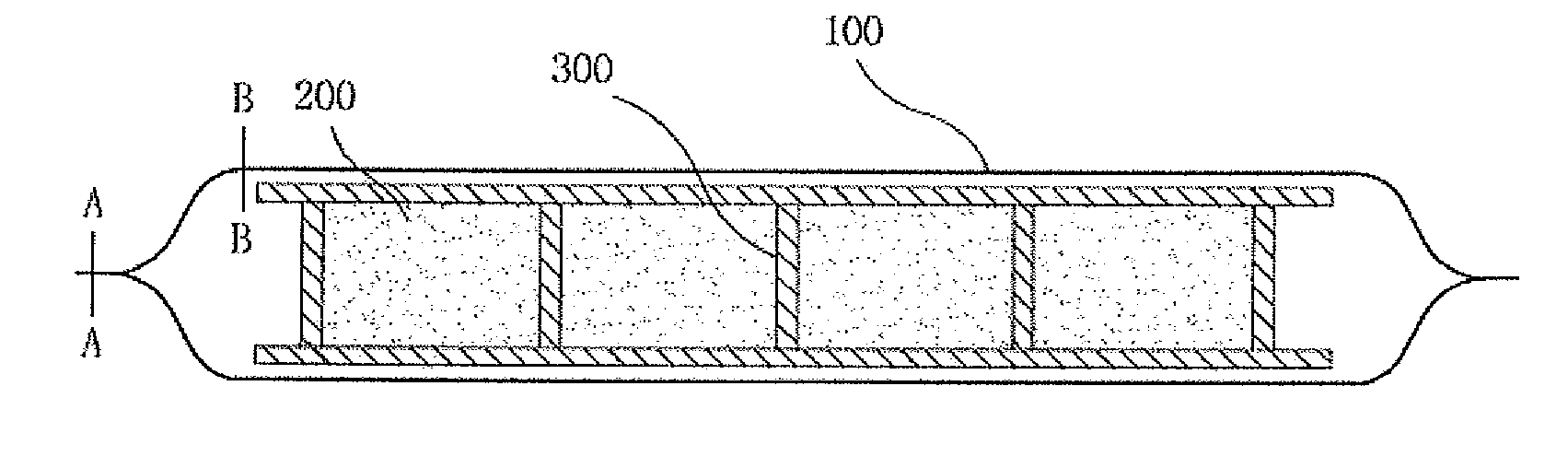
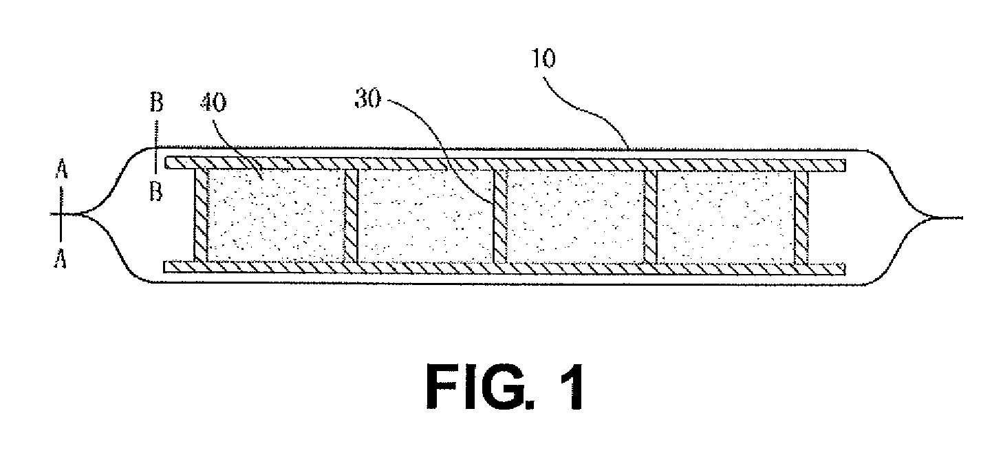
[0053]FIG. 3 is a top view for showing the structure of the vacuum insulator according to a first embodiment of the present invention. FIG. 4 is a cross sectional view of showing an internal structure of the vacuum insulator according to the first embodiment of the present invention.

[0054]As shown in FIGS. 3 and 4, the vacuum insulator of the first embodiment of the present invention includes an internal structure 300, a filler 200 for filling spaces of the internal structure 300, and an envelope 100 for surrounding the internal structure 200.

[0055]The internal structure 300 is designed to have minimal heat transmission to endure the atmospheric pressure. In addition, the internal structure 300 is preferably formed of material having high ratio of a tensile strength to heat conduction coefficient. For example, polymer is used as a result of considering tensile strength, heat conduction rate and manufacture factors. More specifically, Polycarbonate or Polyimide is preferably used amo...

second embodiment

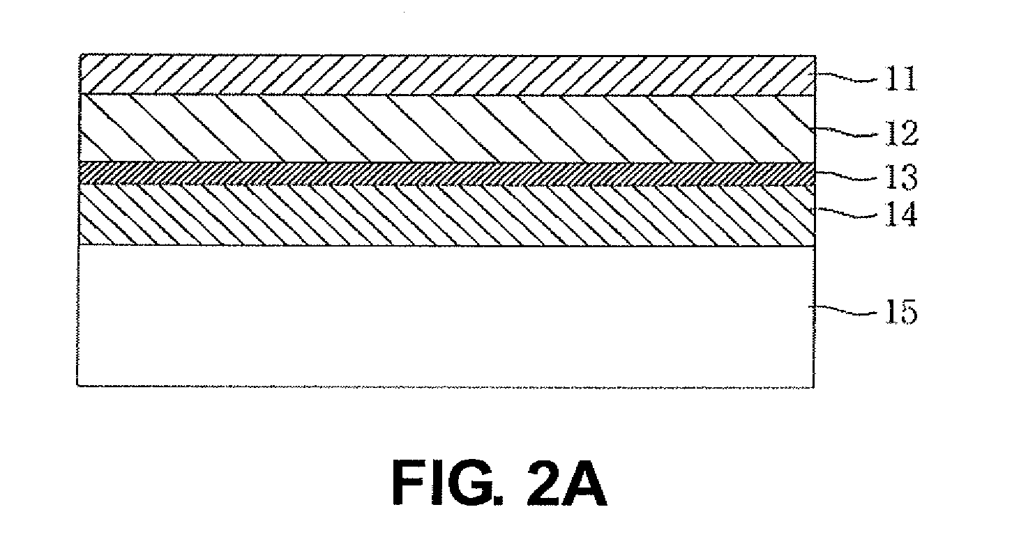
[0081]FIG. 8 is a cross sectional view of the end of the envelope for the vacuum insulator according to a second embodiment according to the present invention (along A-A in FIG. 7).

[0082]As shown in FIG. 8, in the end of the envelope for the vacuum insulator, the upper envelope A and the lower envelope B are adhered by the heat adhesion part H. In the vacuum insulator according to the present invention, since a metal layer 200 is inserted to the heat-adhesion part H to reduce air infiltration through the heat-adhesion part H, a gap between the metal layer 113a of the upper envelope A and the metal layer 113b of the lower envelope B can be decreased. Here, the upper envelope A has a structure in which a Polyethylene terephthalate film PET 111a, a Low density polyethylene film LDPE 112a and a metal layer 113a are stacked. The lower envelope B has a structure in which a Polyethylene terephthalate film PET 111b, a Low density polyethylene film LDPE 112b and a metal layer 113b are stacke...

third embodiment

[0087]FIG. 9 is a cross sectional view of an end of the envelope for the vacuum insulator according to a third embodiment of the present invention (along A-A in FIG. 7).

[0088]As shown in FIG. 9, at an area facing the internal structure in the end of the envelope for the vacuum insulator according to the third embodiment of the present invention, the upper envelope A and the lower envelope B are adhered by a heat adhesion part H. At a area in the end of the envelope, the upper envelope A and the lower envelope B are adhered by polyurethane 300. The upper envelope A is a portion where a Polyethylene terephthalate film PET 121a, Low density polyethylene film LDPE 122a and a metal layer 123a are stacked. In addition, the lower envelope B is a portion where a Polyethylene terephthalate film PET 121b, a Low density polyethylene film LDPE 122b and a metal layer 123b are stacked. In addition, the heat adhesion part H is composed of a LDPE Lowdensity polyethylene film 124a, 124b, and Linear-...


PUM

PropertyMeasurementUnit
aaaaaaaaaa

Abstract

The vacuum insulator includes an internal structure; a filler for filling empty spaces of the internal structure; and an envelope having an upper envelope composed of a metal layer and a polymer layer formed on the metal layer to surround an upper surface of the internal structure, and a lower envelope composed of a metal layer and a polymer layer formed on the metal layer to surround a lower surface of the internal structure, the metal layer of the upper envelope and the metal layer of the lower envelope being opposite to each other, wherein in a certain area along outlines of the upper envelope and the lower envelope, the metal layer of the upper envelope and the metal layer of the lower envelope between which a film composed of a Low density polyethylene LDPE and a Linear-Lowdensity polyethylene LLDPE is inserted, are adhered by heat, and in an area excluding the certain area, the metal layer of the upper envelope and the metal layer of the lower envelope are adhered by polyurethane.

Description

CROSS-REFERENCE TO RELATED APPLICATIONS[0001]This U.S. National stage application claims priority under 35 U.S.C. §119(a) to Korean Patent Application No. 10-2009-0038857, filed in the Republic of Korea on May 4, 2009, and Korean Patent Application No. 10-2009-0099659, filed in the Republic of Korea on Oct. 20, 2009, the entire contents of which are hereby incorporated herein by reference.BACKGROUND OF THE INVENTION[0002]1. Field of the Invention[0003]The present invention relates to a vacuum insulator for being used as insulating material for a building or a refrigerator, etc.[0004]2. Background Information[0005]Half of total energy amount consumed by human being is for heating / cooling houses and commercial buildings, and this rate is same as domestic rate. Considering the fact that supply amount of alternative energy is only 1 to 2% of total energy consumption amount and supply amount for alternative energy is not above 10% even in a long term plan, reducing energy for heating / coo...

Claims


Application Information

Patent Timeline
IPC IPC(8): F25D23/06B32B3/02
CPCB32B3/02B32B15/08B32B27/08B32B27/32B32B27/36Y10T428/239F25D2201/14Y02B80/12Y10T428/231Y10T428/23E04B1/803Y02A30/242Y02B80/10
Inventor SONG, TAE-HOJUNG, HAEYONGKWON, JAE-SUNGJANG, CHOONG HYOKIM, JONGMIN
Owner KOREA ADVANCED INST OF SCI & TECH
Why Eureka
Try Eureka