Fine needle biopsy system and method of use

a biopsy system and needle technology, applied in the field of tissue biopsy needles, can solve the problems of limited application and effectiveness of options, difficult to harvest tissue samples from small organs or glands like lymph nodes or thyroid glands, and significant bleeding, so as to achieve the effect of minimizing tissue trauma

Inactive Publication Date: 2010-11-04
RUSNAK JOSEPH G
View PDF16 Cites 8 Cited by
  • Summary
  • Abstract
  • Description
  • Claims
  • Application Information

AI Technical Summary

Benefits of technology

[0014]The system further includes a needle having a second lumen, a second length greater than the first length, an inner bevel on the distal end, and a second grip on the proximal end. The cannula has a sharpened or pointed distal end such as one found on a hypodermic needle or other cannula (known in the art) that are designed to enter tissue with as little trauma to the tissue as possible. The use of the cannula allows deployment through skin and even muscular tissue with minimal bleeding and bruising. Once the cannula is positioned at the tissue sampling site, the needle is deployed through the lumen of the cannula. The inner bevel defines a mouth that more efficiently receives tissue into the needle lumen by aspiration or by capillary forces.
[0020]The present invention includes a method of sampling tissue that includes a biopsy needle system according to one or more of the embodiments disclosed herein. The cannula is inserted into the patient and positioned adjacent the site of tissue sampling. The biopsy needle is then inserted into the cannula. The needle is pushed into the tissue sampling site to receive tissue into the second passage of the biopsy needle. The deployment of the cannula minimizes tissue trauma during insertion. The tissue sample is removed from the needle. Optionally, another sample can be obtained by the same needle or a new needle by inserting the same needle or the new needle into the held stationary cannula. Then, when sampling is completed, the needle and cannula are removed from the patient.
[0021]In one embodiment, the distal end of the biopsy needle extends beyond the distal end of the cannula a minimum of 0.1 cm and a maximum of about 1 cm. The design prevents the needle from penetrating into the tissue sampling site a distance greater than the distance the needle extends beyond the cannula.

Problems solved by technology

However, such options are limited in their applications and effectiveness.
Tissue samples from small organs or glands like lymph nodes or thyroid glands are especially difficult to harvest due to the relatively small size of the organs or glands (and their respective growths or nodules), location in sites that are uncovered by everyday clothing, and proximity to significant blood vessels.
Furthermore, vascularization in many glands or organs is considerable making the possibility of bleeding a significant issue.
First, open surgery occurs when a patient is cut open to expose the tissue from which a sample is required.
The procedure is invasive and creates a considerable risk of infection and side effects as compared to less invasive means.
The '797 patent indicated, in 1977, that the problem in the biopsy field was that prior biopsy devices had not been successful in providing high quality extracted specimens while at the same time minimizing trauma to the patient and providing easy removability of the specimen from the patient.
At the time of its filing, the '585 patent commented on the state of the art as follows, “In the past, biopsy procedures have been carried out using a hollow needle of varying internal diameter with a tapered distal end and a diagonal cutting edge . . . . Although biopsy needles of this construction have met with success, failure to obtain an adequate core biopsy specimen frequently occurs.
The '440 patent discusses a drawback of fine needle aspiration, “[T]he FNA [fine needle aspiration] biopsy needle procedure fails to collect a sample of sufficient size to enable definitive pathological results.
When this happens, the physician must repeat the procedure causing additional trauma to the body part undergoing biopsy and creating additional risk of an adverse event.”
Kim concludes, “However, the achievement of optimal results of the thyroid FNA, with increased efficacy and decreased inadequacy results, requires not only a skillful aspiration technique and attention to the factors that affect material adequacy but also awareness of the indications for and limitations of FNA biopsy . . . . US-guided FNA yields an inadequate specimen in 10%-20% of procedures .

Method used


Image

  • Fine needle biopsy system and method of use
  • Fine needle biopsy system and method of use
  • Fine needle biopsy system and method of use

Examples


Embodiment Construction

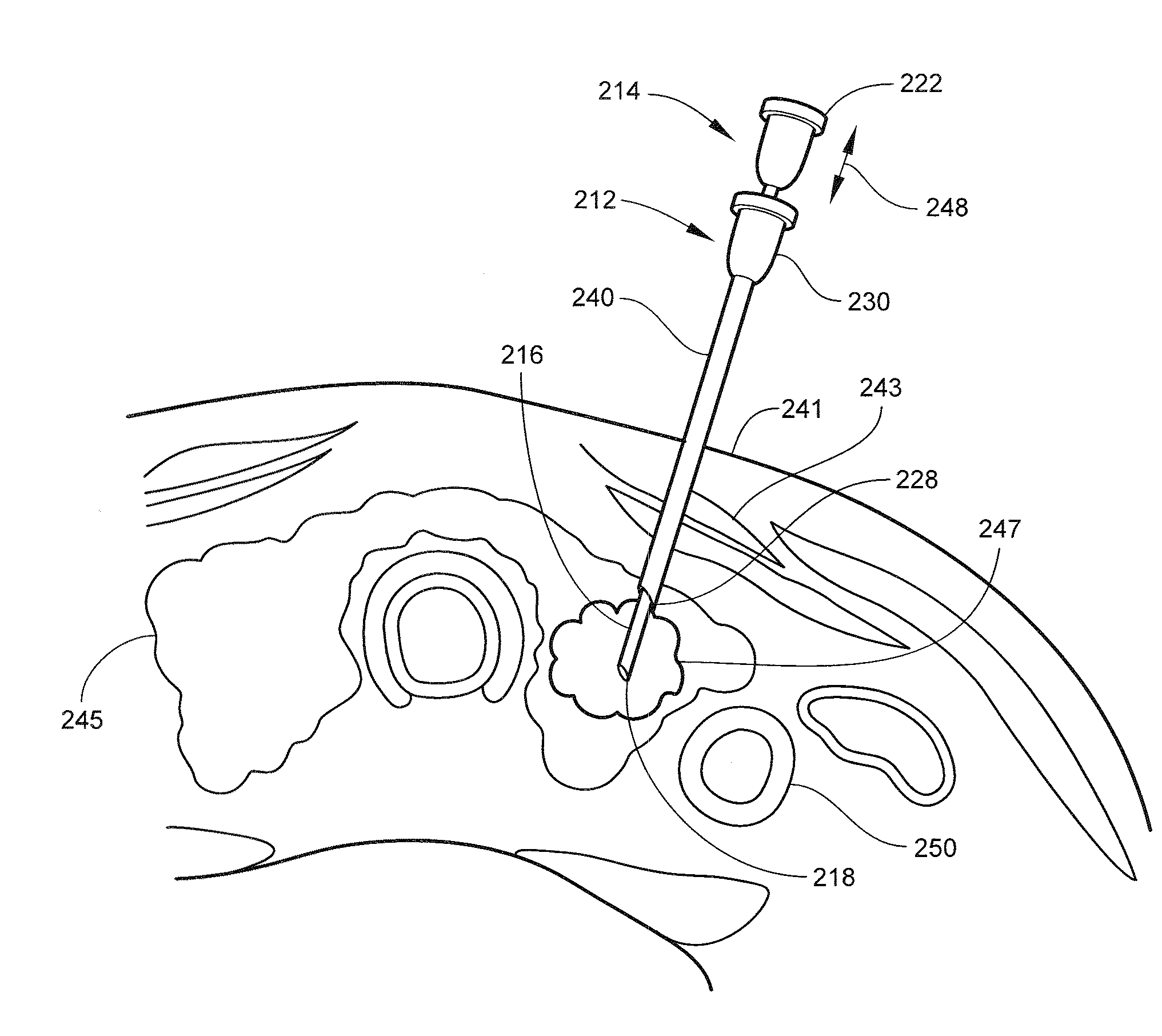
[0036]As noted, the present invention is a fine needle biopsy system that has improved delivery to the site of tissue biopsy. The biopsy system uses a cannula to deliver the needle to the tissue biopsy site. The needle is designed to more efficiently harvest or sample tissue. The device is capable of being positioned with minimal pain, tissue trauma, and bleeding. The harvesting of the tissue is capable of adequate sample size without unnecessary tissue damage.

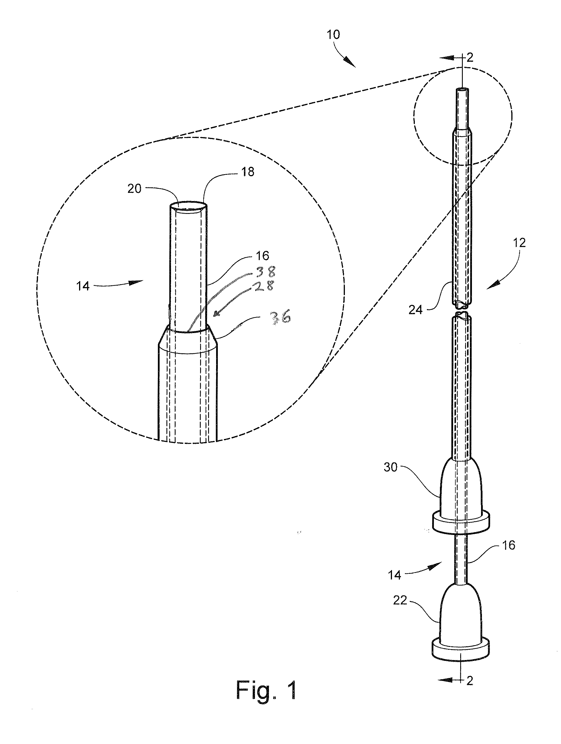
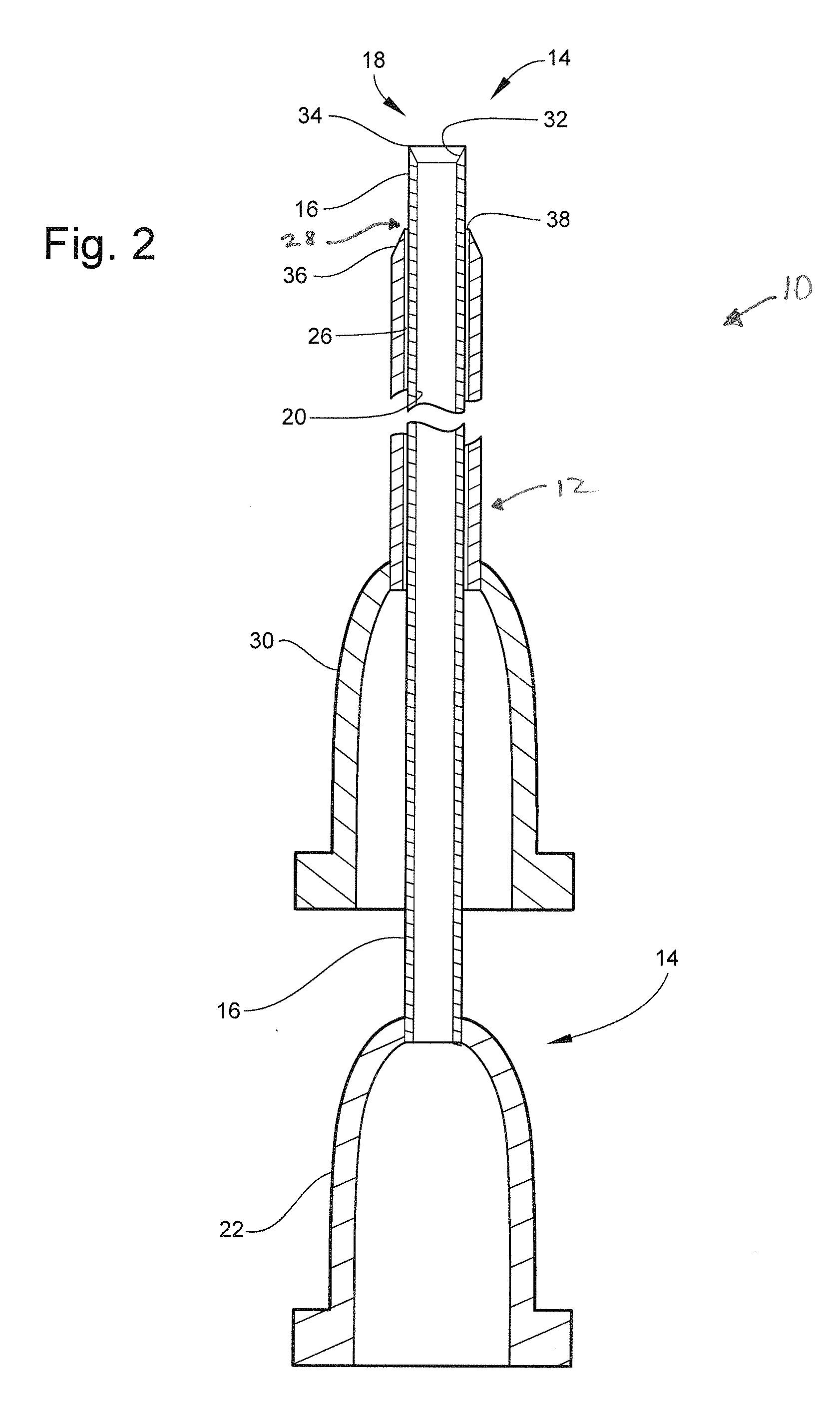
[0037]With reference to FIG. 1, the fine needle biopsy system 10 includes a cannula 12 and a needle 14. Also shown are a cutaway view in FIG. 2 and an enlarged distal end view in FIG. 3. The cannula 12 of one embodiment has a grip that comprises a luer fitting 30 and a tubular cannula shaft 24 that defines the cannula lumen 26.

[0038]The cannula tip 28 has an outer bevel 36 that causes the tip 28 of the cannula 12 to form a cutting edge 38 on the inside surface of the cannula 12 which forms a generally frusto-conical shape. An ...


PUM


Abstract

The present invention includes a biopsy needle system comprising a tubular cannula having a first longitudinal passage, a first length, and a first grip on the proximal end of the cannula. The tubular biopsy needle has a second longitudinal passage, a second length greater than the first length, an inward beveled distal end, and a second grip on the proximal end. The biopsy needle is both sized and configured to fit within the first passage.

Description

FIELD OF THE INVENTION[0001]The present invention relates generally to tissue biopsy needles and the use to harvest tissue in a minimally invasive manner.BACKGROUND OF THE RELATED ART[0002]The development of non-invasive assays for diagnosing certain types of cancer has provided practitioners with some options for diagnosis of cancer and other related disease without the need for tissue biopsy. However, such options are limited in their applications and effectiveness. Still, the most definitive test for cancer or related disease is tissue biopsy. Tissue biopsy occurs when a sample of tissue from a site that is believed to be diseased is harvested and analyzed by a pathologist to determine the nature of the tissue, whether it is healthy tissue, benign tissue growth, or cancerous tissue.[0003]Tissue samples from small organs or glands like lymph nodes or thyroid glands are especially difficult to harvest due to the relatively small size of the organs or glands (and their respective gr...

Claims


Application Information

Patent Timeline
Patent Type & Authority Applications(United States)
IPC IPC(8): A61B10/02
CPCA61B10/0233A61B10/0266A61B17/3417A61B10/0283A61B17/34A61B10/0275
Inventor RUSNAK, JOSEPH G.
Owner RUSNAK JOSEPH G
Why Eureka
Try Eureka