Intervertebral implant

a technology of intervertebral implants and stents, which is applied in the field of intervertebral implants, can solve the problems of inability to accept tensile force, inability to join the fibre system with the cover plate, and difficulty in fixing the integrated fibres on the end plate, etc., and achieves the effect of less danger of fissure formation in the sheathing body, limited disadvantage of central buckling, and easy insertion

Inactive Publication Date: 2010-11-04
DEPUY SYNTHES PROD INC
View PDF35 Cites 3 Cited by
  • Summary
  • Abstract
  • Description
  • Claims
  • Application Information

AI Technical Summary

Benefits of technology

[0012]the fibre system can be first wound around the central part and following this poured into an elastomer forming the elastic sheathing body, so that the sheathing, enveloping the central part, can be easily produced,
[0020]In a further embodiment the fibre system is only partially embedded in the elastic sheathing body, while the fibre system has a radial thickness δ relative to the central axis and the elastic sheathing body has a radial thickness d, and the δ / d×100% ratio is in a range of 80% and 350%. By virtue of this the advantages can be achieved, that the large relative movements in the peripheral region of the cover plates occurring during a flexion / extension movement or a lateral movement of the adjacent bodies of the vertebra are not subjected to a great resistance by the elastic sheathing body and due to this the danger of a fissure formation in the sheathing body is slighter.
[0024]In yet another embodiment the entire fibre system is anchored on the cover plates, so that greater tensile forces can be accepted by the fibre system, and consequently the intervertebral implant obtains a great torsional rigidity.
[0037]In yet another embodiment the central part is essentially hollow-cylindrical, hollow-prismatic or is a body of rotation, an ellipsoid, a partial sphere or barrel-shaped with an axis of rotation that is coaxial with the central axis. By virtue of such configurations the advantage, that the positions of the axes of rotation of the adjacent intervertebral discs correspond, as far as possible, to that of the natural intervertebral disc, can be achieved.
[0039]In a further embodiment of the intervertebral implant according to the invention a closing plate is fastened on each cover plate for placing the adjacent bodies of the vertebra on the base plate or cover plate, each of the said closing plate having an external surface at right angles to the central axis with a macroscopic structure. The structure may be, for example, in the form of teeth. The macroscopic structure allows a primary stabilisation of the intervertebral implant immediately after the operation. Thus a mechanical anchoring of the intervertebral implant at a time when the growing of the bone on the intervertebral implant has not yet taken place, can be achieved.

Problems solved by technology

In the case of the prosthesis disclosed in U.S. Pat. No. 4,911,718 Lee, although the individual fibres are integrated in the laminate that is made from an elastomer or another type of synthetic material, their ends are, however, adhered only to the end plates, so that they do not surround the core and consequently, in the case of a radial expansion of the core, cannot accept any tensile force.
When adhering the lateral walls, cut out from the fibrous matrix compound, to the end plate, a fixing of the integrated fibres on the end plate is quite difficult, only the cross-section of the fibre offers a contact surface for the chemical joint.
A disadvantage of this known prosthesis is that the fibre system, joined with the cover plates, is either not embedded in the sheathing body or in another embodiment is embedded in a multi-layer laminate of an elastomer.

Method used


Image

  • Intervertebral implant
  • Intervertebral implant
  • Intervertebral implant

Examples


Embodiment Construction

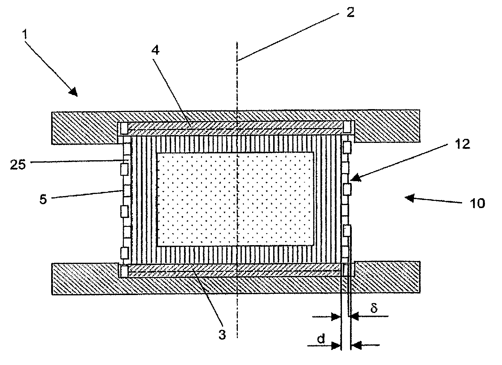
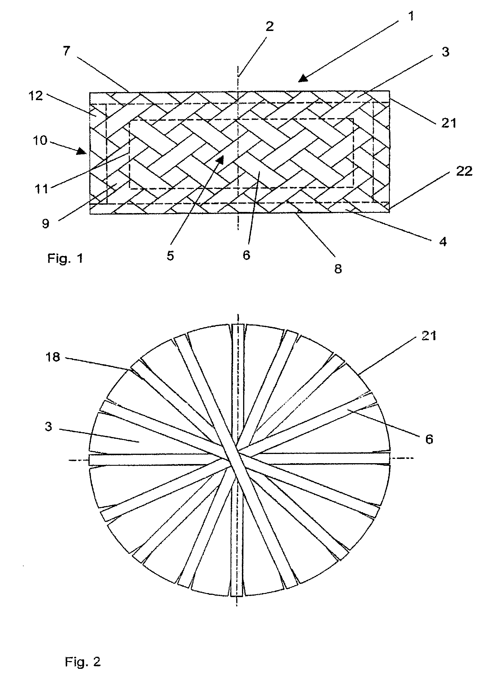
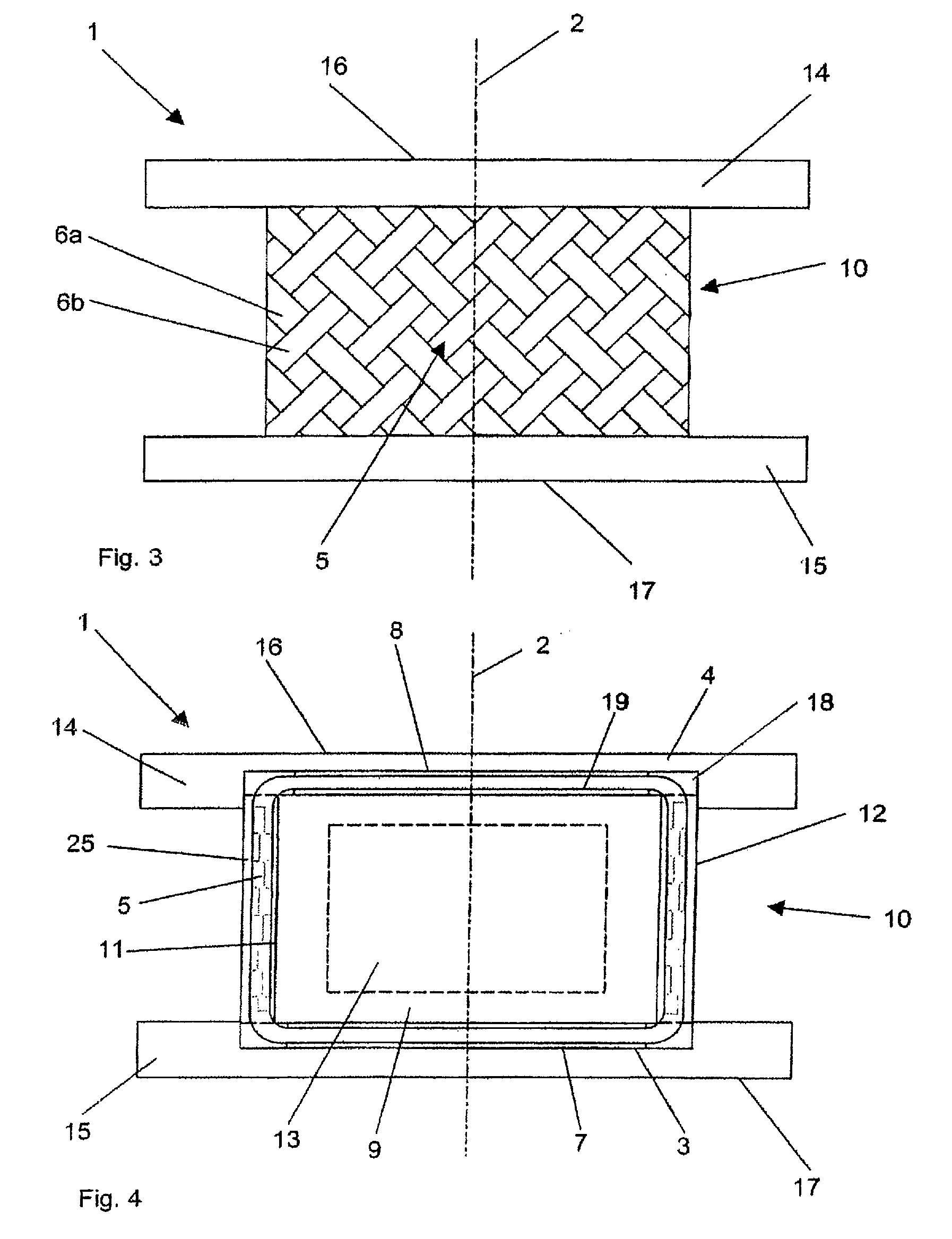
[0058]FIGS. 1 and 2 illustrate an embodiment of the intervertebral implant 1 according to the invention, that comprises a top cover plate 3 and a bottom cover plate 4, each with an external surface 7, 8 extending at right angles to the central axis 2 and having a lateral surface 21, 22 on the periphery. Between the cover plates 3, 4 there is a central part 10 provided with a central cavity 11 and a sheathing 12, that surrounds the fibre system 5. For the purpose of anchoring the fibres 6 of the fibre system 5 on the cover plates 3, 4, each of the peripheral lateral surfaces 21, 22 has grooves 18, distributed on the circumference and radially protruding into the lateral surfaces 21, 22, so that the fibre system 5 can be anchored in these grooves 18. In the central cavity 11 there is an elastically deformable formed body 9 with an incompressible core, preferably a liquid core 13. Due to the incompressibility of the liquid core 13 during a compression of the cover plates 3, 4 parallel ...


PUM

PropertyMeasurementUnit
anglesaaaaaaaaaa
anglesaaaaaaaaaa
anglesaaaaaaaaaa

Abstract

An intervertebral implant including a central axis, a bottom cover plate and a top cover plate, which are respectively provided with an exterior surface that extends transversal to the central axis, and a central part.

Description

CROSS-REFERENCE TO RELATED APPLICATION[0001]This application is a continuation of U.S. patent application Ser. No. 12 / 198,761, filed on Aug. 26, 2008, which is a continuation of U.S. patent application Ser. No. 10 / 553,495, now U.S. Pat. No. 7,429,270, filed on Jul. 25, 2006, which is a National Stage application of PCT / CH03 / 00247, filed on Apr. 14, 2003, the entire disclosures of which are incorporated herein by reference.FIELD OF THE INVENTION[0002]The invention concerns an intervertebral implant.BACKGROUND OF THE INVENTION[0003]An intervertebral disc prosthesis of the generic type is known from U.S. Pat. No. 4,911,718 Lee. This known intervertebral disc prosthesis comprises a central core, that is so formed from a biocompatible elastomer, that it is almost corresponds to that of the nucleus pulposus of a natural intervertebral disc, as well as from a multi-layer laminate from fibres bound in an elastomer, arranged around the core. Each laminate layer has its own yarn system, so th...

Claims


Application Information

Patent Timeline
Patent Type & Authority Applications(United States)
IPC IPC(8): A61F2/44A61F2/00A61F2/30B60R11/00B60R11/02
CPCA61F2/30965A61F2310/00023A61F2/442A61F2002/30009A61F2002/30448A61F2002/30462A61F2002/30563A61F2002/30581A61F2002/30827A61F2002/30841A61F2002/4495A61F2220/005A61F2220/0075A61F2250/0028A61F2/441A61F2/44
Inventor BAUMGARTNER, DANIELWYMANN, MARTINGAGO HO, MARIOBURRI, ADRIAN
Owner DEPUY SYNTHES PROD INC
Why Eureka
Try Eureka