Double clutch transmission

a transmission and double clutch technology, applied in the direction of mechanical equipment, transportation and packaging, gearing, etc., can solve the problems of unconsiderable structural space, unfavorable installation in vehicles, so as to achieve low production costs of the transmission

Active Publication Date: 2010-11-11
ZF FRIEDRICHSHAFEN AG
View PDF12 Cites 11 Cited by
  • Summary
  • Abstract
  • Description
  • Claims
  • Application Information

AI Technical Summary

Benefits of technology

[0006]The purpose of the present invention is to propose a dual-clutch transmission of the type described at the start with which, on the one hand, the shift-under-load transmission ratio steps can be produ

Problems solved by technology

To produce the desired transmission ratio steps with the known dual-clutch transmissions, a substantial number of wheel planes are required, so that the structural space required for installi

Method used


Image

  • Double clutch transmission
  • Double clutch transmission
  • Double clutch transmission

Examples


first embodiment

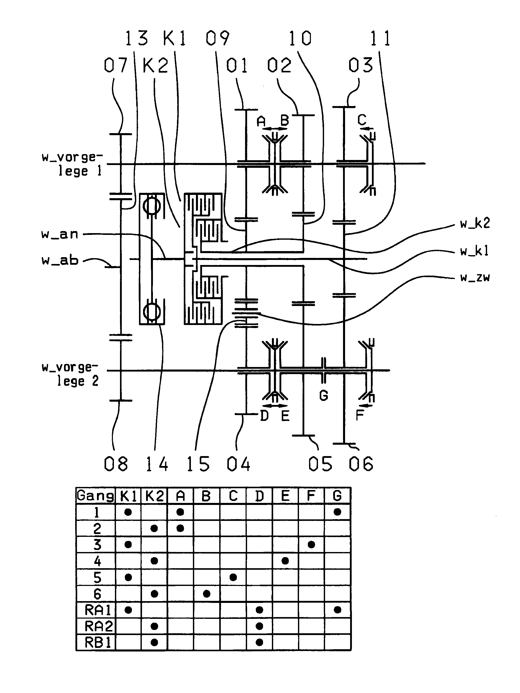
[0030]In the first embodiment, variant fixed gearwheels 09, 10 are arranged rotationally fixed on the second transmission input shaft w_K2 and a fixed gearwheel 11 is so arranged on the first transmission input shaft w_K1. In this way, three wheel planes 01-04, 02-05, 03-06 are formed as dual wheel planes.

[0031]In the first wheel plane 01-04, the fixed gearwheel 09 of the second transmission input shaft w_K2 meshes with the idler gearwheel 01 of the first countershaft w_vorgelege1. Furthermore, an idler gearwheel 15 on an intermediate shaft w_zw meshes with both the fixed gearwheel 09 of the second transmission input shaft w_K2 and with the idler gearwheel 04 of the second countershaft w_vorgelege2. In this way, a rotation direction reversal can be provided in order to produce reverse gears RA1, RA2 and RB1. It is also possible for the idler gearwheel 15 to be made as a step wheel. For the rotation direction reversal, the idler gearwheel 01 of the first countershaft w_vorgelege1 can...

second embodiment

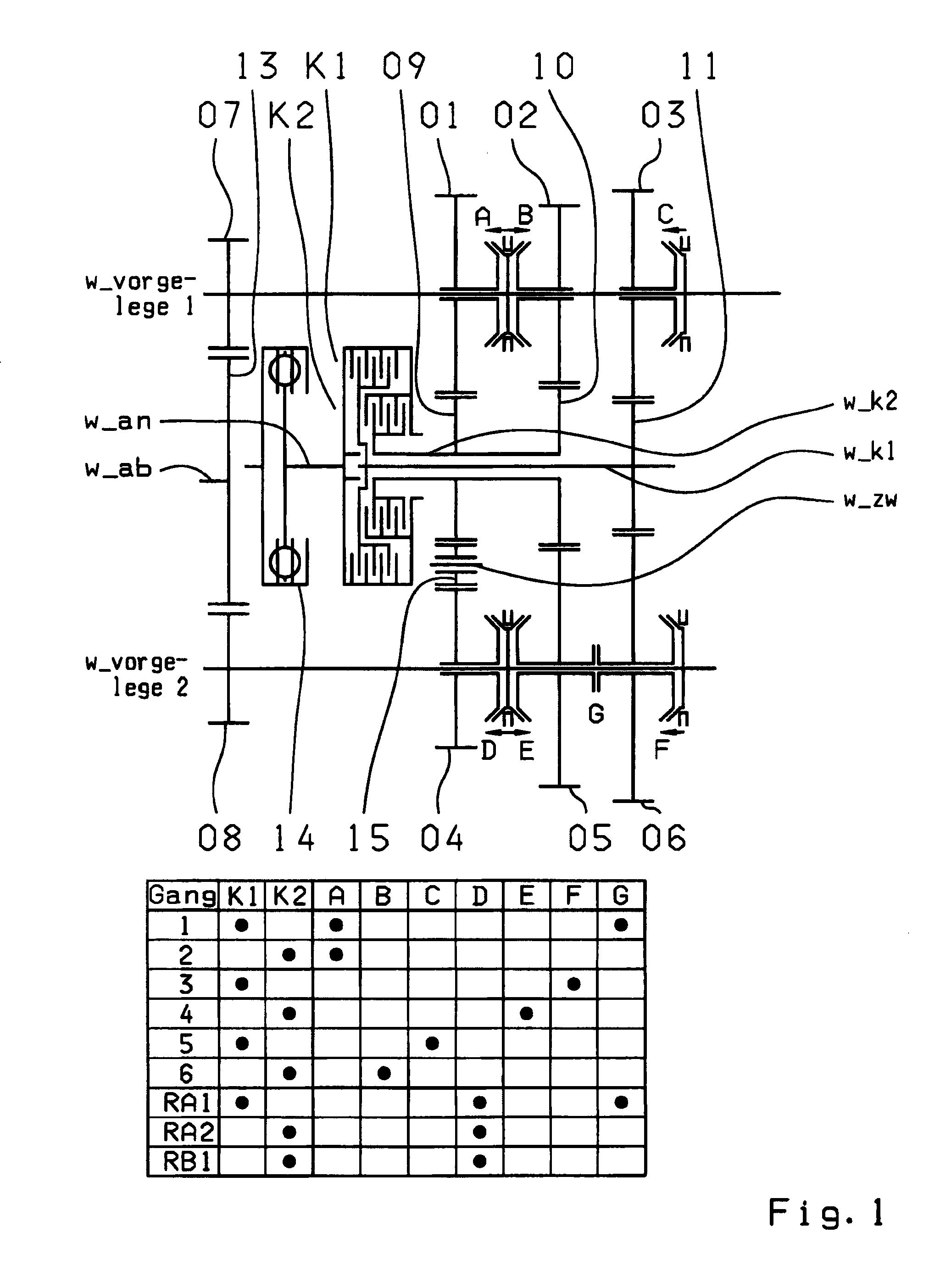
[0042]In the second embodiment variant, the third wheel plane 03-11 is created by the fixed gearwheel 11 of the first transmission input shaft w_K1, which meshes with the idler gearwheel 03 of the first countershaft w_vorgelege1. The fourth wheel plane 12-06 is created by the fixed gearwheel 12 of the first transmission input shaft w_K1, which meshes with the idler gearwheel 06 of the second countershaft w_vorgelege2. Thus, in the third wheel plane 03-11 and the fourth wheel plane 12-06, the fixed gearwheels 11 and 12 of the first transmission input shaft w_K1 mesh, in each case, with only one idler gearwheel 03 or 06, respectively. This gives the advantage of a freer choice of transmission ratio, in contrast to wheel planes in which the idler gearwheels engage with the fixed gearwheel on both sides.

[0043]Accordingly, in the second embodiment variant shown in FIG. 2, the first and second wheel planes 01-04 and 02-05 are dual wheel planes. In contrast, the third and fourth wheel plan...

third embodiment

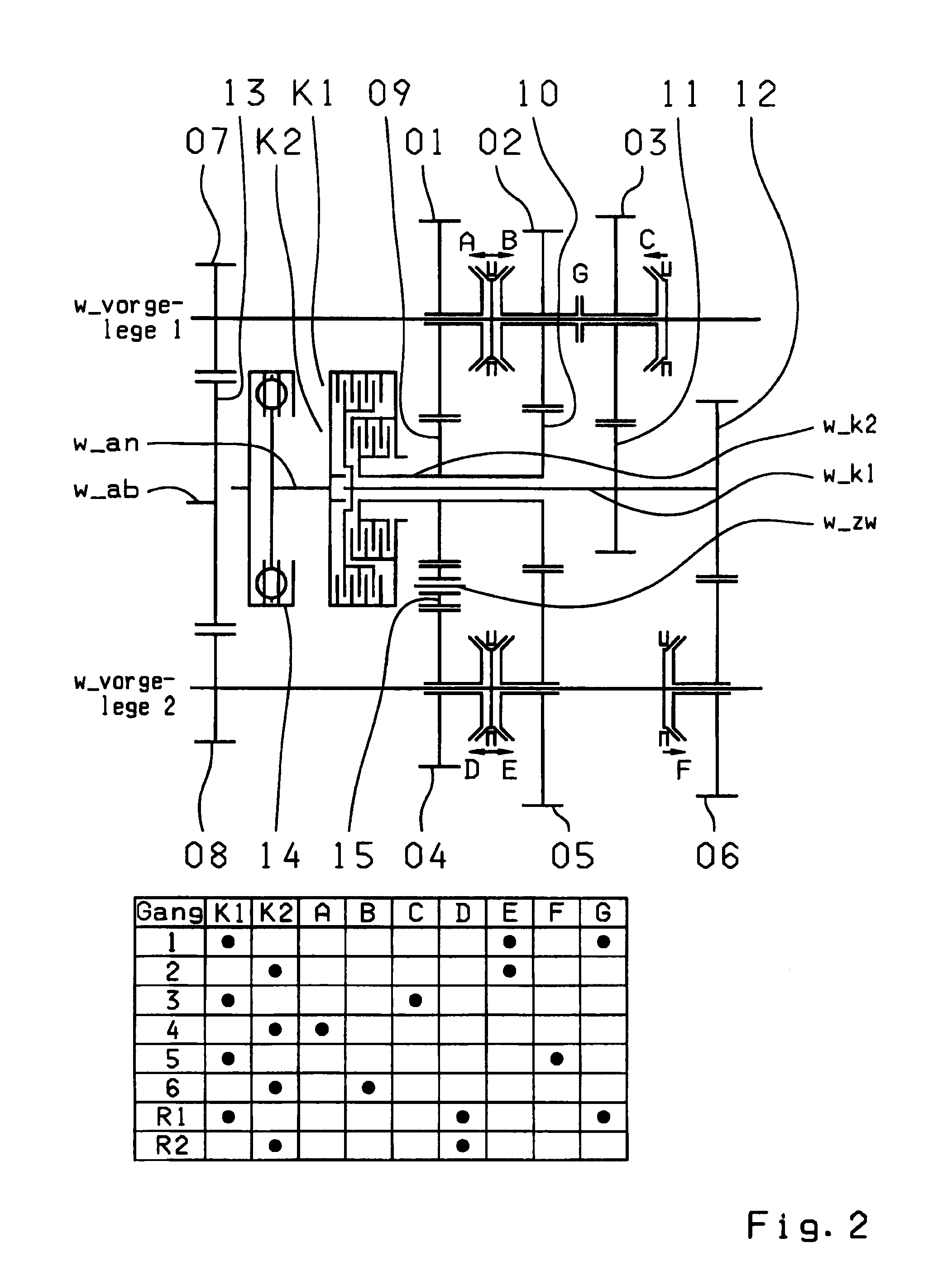
[0055]In the third embodiment variant, the additional shifting element G, for producing the winding gear or for coupling the two part-transmissions, is arranged on the second countershaft w_vorgelege2 between the second wheel plane 02-04 and the third wheel plane 03-05.

[0056]The table in FIG. 3A shows an example shifting scheme for the third embodiment variant of the six-gear dual-clutch transmission.

[0057]According to this, the first forward gear 1 can be engaged as a winding gear by means of the first clutch K1, the activated shifting element G and the coupling device A-B when pushed in the B direction. The second forward gear 2 is engaged by means of the second clutch K2 and the coupling device A-B pushed in the B direction. In contrast, the third forward gear 3 is engaged by means of the first clutch K1 and the coupling device E-F when pushed in the E direction, and the fourth forward gear 4 can be engaged with the second clutch K2 and the coupling device A-B when pushed in the ...


PUM


Abstract

A dual-clutch transmission with two clutches (K1, K2) whose input sides are connected to a drive input shaft (w_an) and whose output sides are respectively connected to one of two transmission input shafts (w_K1, w_K2) arranged coaxially with one another. Idler gearwheels (01, 02, 03, 04, 05, 06) are mounted to rotate on at least two countershafts (w_vorgelege1, w_vorgelege2) while fixed gearwheels (09, 10, 11) are rotationally fixedly connected on the two transmission input shafts (w_K1, w_K2). A plurality of coupling devices (A-B, C, D-E, D, E-F, F) connect the idler gearwheels (01, 02, 03, 04, 05, 06) of the two countershafts (w_vorgelege1, w_vorgelege2) with a respective drive output gearwheel (07, 08) fixed on each of the two countershafts (w_vorgelege1, w_vorgelege2). At least one shifting element (G) couples the two transmission input shafts (w_K1, w_K2) such that at least six shift-under-load forward gears (1, 2, 3, 4, 5, 6) and at least one reverse gear (RA1, R1) can be engaged. The transmission has three wheel planes (01-04; 02-05; 03-06) or four wheel planes (01-04, 01-09; 02-05, 02-04; 03-11, 03-05; 12-06) arranged in such manner that at least one shift-under-load winding gear can be engaged by the shifting element (G).

Description

[0001]This application is a National Stage completion of PCT / EP2008 / 063431 filed Oct. 8, 2008, which claims priority from German patent application serial no. 10 2007 049 267.9 filed Oct. 15, 2007.FIELD OF THE INVENTION[0002]The present invention concerns a dual-clutch transmission for a vehicle.BACKGROUND OF THE INVENTION[0003]From the document DE 103 05 241 A1, a six-gear or seven-gear dual-clutch transmission is known. The dual-clutch transmission has two clutches, each connected on its input side to the drive input shaft and, on its output side, to one of the two respective transmission input shafts. The two transmission input shafts are arranged coaxially with one another. Further, two countershafts are arranged axis-parallel to the two transmission input shafts, whose idler gearwheels mesh with fixed gearwheels of the transmission input shafts. Moreover, coupling devices are held rotationally fixed but able to move axially, on the countershafts, in order to be able to shift th...

Claims


Application Information

Patent Timeline
IPC IPC(8): F16H3/093
CPCF16H3/006F16H3/093F16H2003/0807F16H2003/0826Y10T74/19228F16H2200/0052F16H2200/0086F16H2200/0091Y10T74/19065F16H2003/0931
Inventor RIEGER, WOLFGANG
Owner ZF FRIEDRICHSHAFEN AG
Why Eureka
Try Eureka