
Armor protection against explosively-formed projectiles

a technology of explosively formed projectiles and armor, applied in reactive armour, protective equipment, weapons, etc., can solve the problems of heavy vehicles, excessive bulky vehicles, and difficult to defeat ieds, and achieve the effect of saving weigh

Inactive Publication Date: 2010-11-11
INTPROP HLDG
View PDF99 Cites 29 Cited by
  • Summary
  • Abstract
  • Description
  • Claims
  • Application Information

AI Technical Summary

Benefits of technology

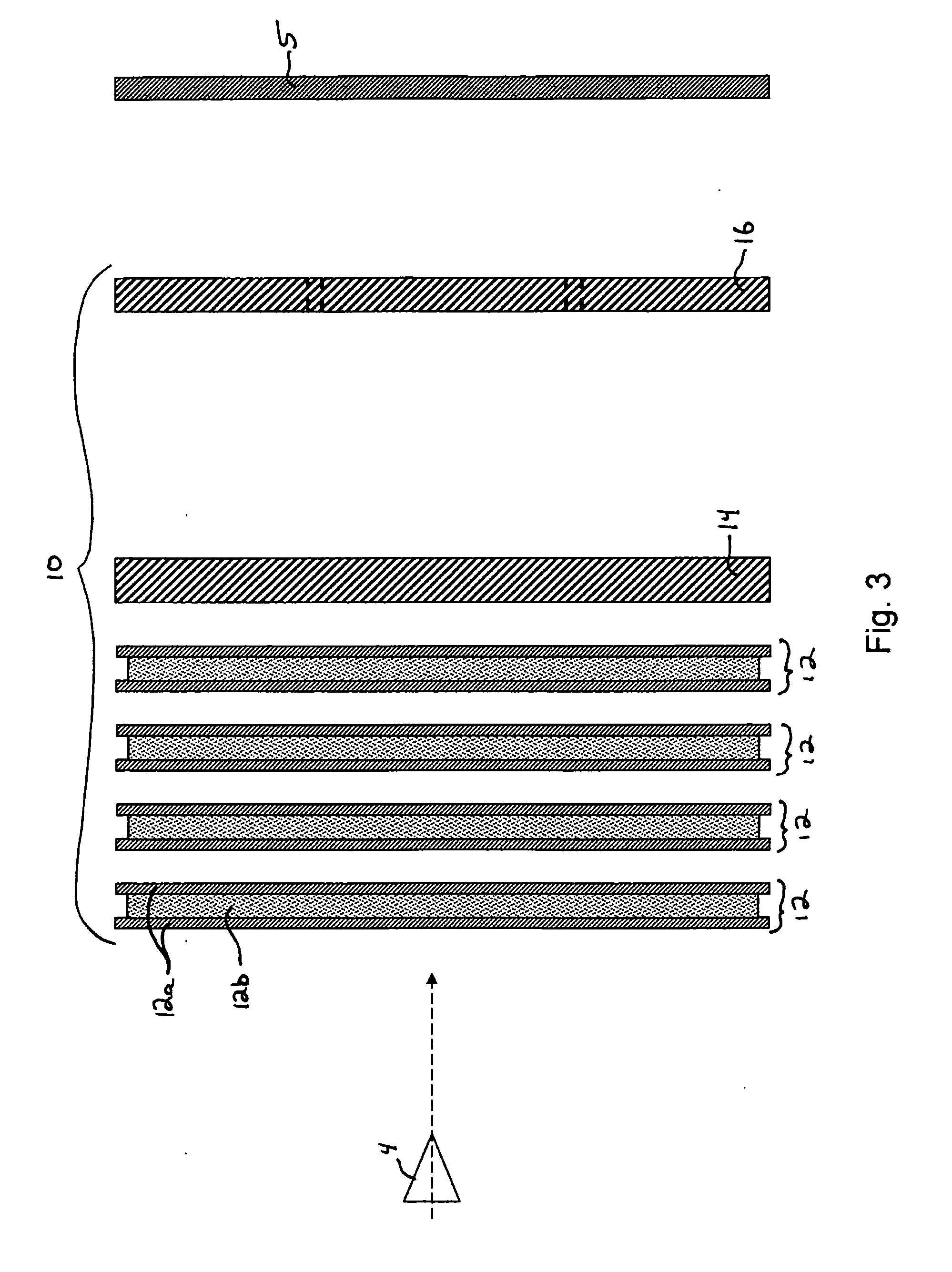
[0006]A hybrid armor architecture adapted to protect a body panel from a high-energy ballistic threat is disclosed. The architecture includes a laminate reactive armor panel, an armor plate disposed behind the laminate reactive armor panel and a flyer plate disposed behind the armor plate. The laminate reactive armor panel has a layer of non-explosively reactive material sandwiched between outer layers of ductile material. The displacement of such a ductile plate or a portion thereof is configured to move toward and impact projectile causing a disturbance in its trajectory. This is usually followed by an armor plate or armor body that bears a significant part of the projectile impact and further destabilize it. Finally a break-away plate or flyer plate or plates are provided close to the body panel so that on impact of a high-energy ballistic destabilized projectile with the flyer plate or the portion thereof, to thereby increase the total area of impact with the body panel relative to the projectile alone.
[0008]A hybrid armor architecture adapted to protect a body panel from a high-energy ballistic threat is further disclosed. The architecture includes a plurality of laminate reactive armor panels, each panel having a layer of non-explosively reactive material sandwiched between outer layers of ductile material, wherein the laminate reactive armor panels are spaced from one another a distance of 0.125 to 0.5 inch. An armor plate having a thickness of 0.1 to 0.75 inch disposed 0.5 to 1 inch is disposed behind the laminate reactive armor panel that is to be positioned nearest the body panel in use. A flyer plate having a thickness of 0.1 to 0.75 inches is disposed 4 to 8 inches behind the armor plate. The flyer plate or a portion thereof is configured to move toward and impact the body panel on impact of a high-energy ballistic projectile with the flyer plate or the portion thereof, to thereby increase the total area of impact with the body panel relative to the projectile alone.
[0009]The number of each type of panel / plate in each part of the architecture, their dimensions and material composition are dependent upon the severity of the threat. For highly energetic threats, it may be necessary or desirable to deploy additional numbers of panels / plates in each part of the architecture or in only some part of the architecture. Alternatively, depending on the threat level, the hybrid armor architecture can comprise a laminate reactive armor panel and at least one component selected from either an armor plate disposed behind the laminate reactive armor panel or a flyer plate disposed behind the laminate reactive armor panel. Nonetheless the embodiments described herein can provide significant weight savings relative to an comparable amount of RHA or other similar steel armor solutions.

Problems solved by technology

Improvised explosive devices (IEDs) present a significant challenge to conventional armor architectures.
One type of IED that has been particularly difficult to defeat is that which produces explosively-formed projectiles (or EFPs).
Therefore, to defeat such threats using conventional materials, the thickness of the armor layers or plates is increased, making the vehicles excessively bulky, heavy and prone to mechanical failures.
Therefore, a vehicle that needs a protective area of 100 square feet would require steel / RHA armor in excess of 16,000-20,000 lbs., making it practically an impossible solution.

Method used


Image

  • Armor protection against explosively-formed projectiles
  • Armor protection against explosively-formed projectiles
  • Armor protection against explosively-formed projectiles

Examples


example 1

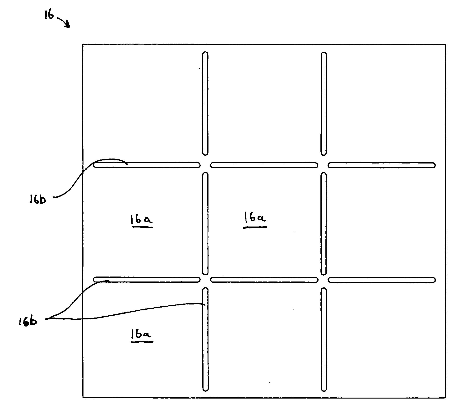
[0053]An armor architecture consisting of 7 layers of laminate non-reactive panels 12 each consisting of two ⅛″ aluminum plates (12a) sandwiching a ¼″ LDPE (low density polyethylene sheet) (12b) arranged in a zig-zag manner (shown in FIG. 6b), followed by a flyer plate 16 consisting of ⅜″ RHA, which all together weighed approximately 47 (+ / −2) pounds per square foot, has been shown to defeat an EFP threat provided in the form of 460 grams of copper propelled from an EFP device by 7.5 lbs. of C4 high explosive when the armor was placed with the flyer plate 16 spaced at 4.5 feet from a ⅜-inch thick RHA panel to simulate the skin (body panel 5) of a typical armored military vehicle. High speed photography was used determine that the velocity of the EFP was in the range of 2.2 to 2.6 km / sec. In testing with these parameters, the ⅜-inch thick RHA skin exhibited no perforation and only a small indentation less than ⅛ inch deep. As a comparison, the identical threat penetrated approximatel...

example 2

[0054]An armor arrangement was constructed as follows: five laminate non-reactive panels 12 were constructed in such a way that each panel 12 consisted of two ⅛″ aluminum plates (Alloy 6061) (12a) with a ¼″ polyethylene sheet (12b) in intimate contact. The panels 12 were spaced approximately ½″ apart and were oriented at roughly an 11-degree angle with respect to the horizontal plane of the following armor plate consisting of a ⅜″ RHA plate (14) and ½″ fiberglass composite (˜70 vol % E-Glass). A gap of about 1.5″ between the RHA plate and the composite. A flyer plate made of ⅜″ RHA was disposed behind the armor plate and spaced at 2″ from the vehicle skin to be protected. The overall area density of this arrangement was about 58 lbs / ft2. The EFP threat was identical to Example 1. Projectile was aimed at zero obliquity with respect to the armor plate and the flyer plate. The vehicle skin consisted of ⅜″RHA plate as an outer layer, 2″ fiberglass composite in the middle and ¼″ RHA plat...

example 3

[0055]An armor architecture according to Example 2 was constructed except only four panels (12) were used instead of five. As a result, the areal density of this armor arrangement was reduced to about 53 lbs / ft2. The EFP threat was identical to Example 1. After the test, the outer skin of the vehicle was damaged or punctured, the 2″ fiberglass panels showed cracking, and there was no damage to vehicle's interior plate. As compared to an RHA armor panel alone, weight savings was about 62%. As seen in this and the above Examples, there is a relationship between the areal density of the armor architecture and the acceptable level of damage to the vehicle skin.


PUM

PropertyMeasurementUnit
distanceaaaaaaaaaa
thicknessaaaaaaaaaa
thicknessaaaaaaaaaa

Abstract

A hybrid armor architecture is provided that is effective against explosively-formed and other high-energy ballistic projectiles. The architecture includes at least one laminate reactive armor panel including a layer of non-explosively reactive material sandwiched between outer layers of a ductile material, an armor plate disposed behind the laminate reactive armor panel, and a flyer plate disposed behind the armor plate. The flyer plate or a portion thereof is configured to move toward and impact a body panel that is being protected on impact of a high-energy ballistic projectile with the flyer plate or the portion thereof, to thereby increase the total area of impact with the body panel relative to the projectile alone.

Description

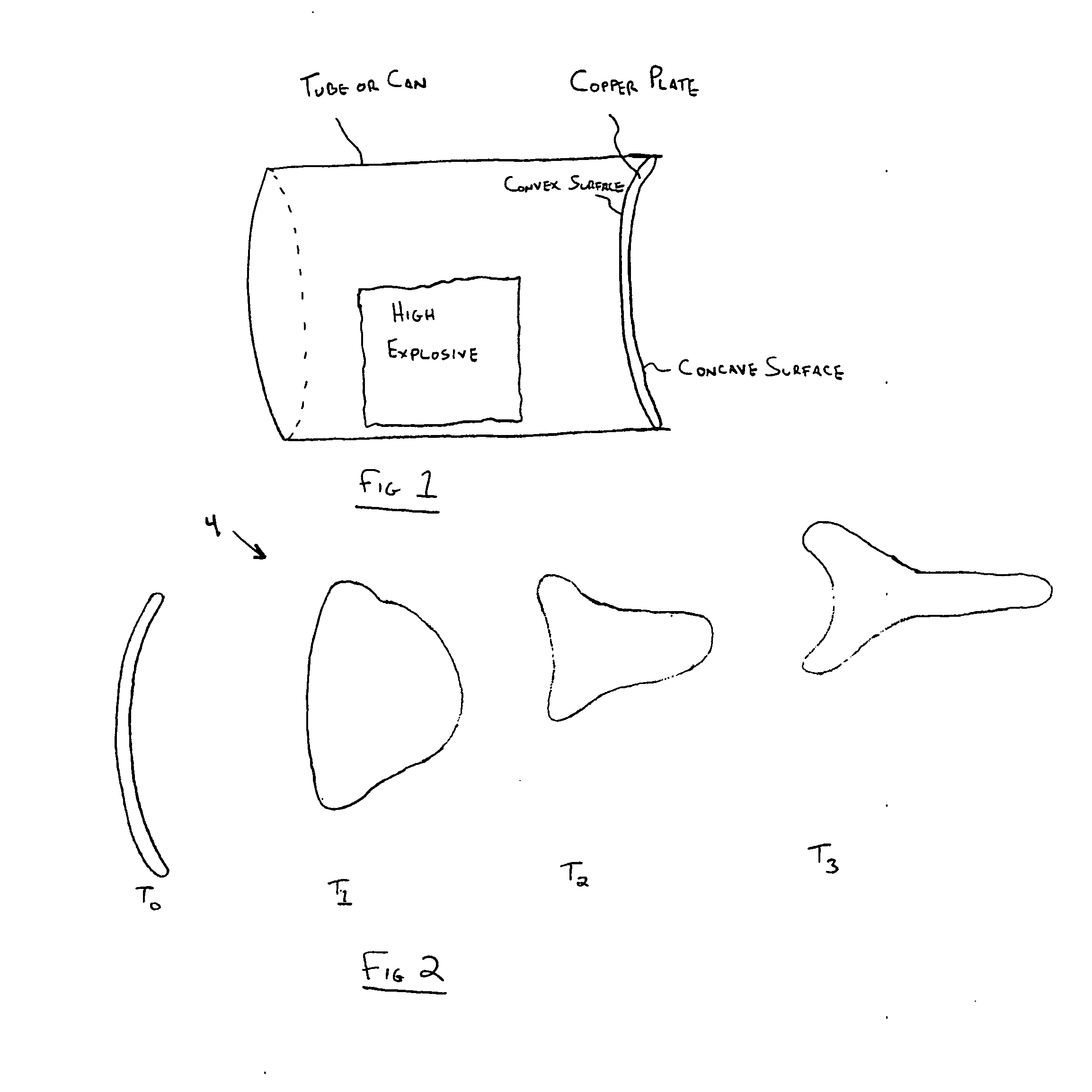
[0001]This application claims the benefit of U.S. provisional applications Ser. Nos. 60 / 988,468 filed Nov. 16, 2007 and 61 / 004,853 filed Nov. 30, 2007, the contents of which are incorporated herein by reference.BACKGROUND OF THE INVENTION[0002]Improvised explosive devices (IEDs) present a significant challenge to conventional armor architectures. One type of IED that has been particularly difficult to defeat is that which produces explosively-formed projectiles (or EFPs). One such EFP device is schematically illustrated in FIG. 1, wherein a high explosive (such as plastic explosive or C4) is placed in a tube or a can having an open end. A bowl-shaped sheet of metal, typically copper, is placed at the open end with its concave surface facing outward, so that the high explosive is enclosed within the tube or can behind the copper sheet. This improvised device is positioned so that the concave surface of the copper sheet faces the target or the location where the target is expected. Wh...

Claims


Application Information

Patent Timeline
Patent Type & Authority Applications(United States)
IPC IPC(8): F41H5/04
CPCF41H5/007F41H5/013F41H5/0457F41H5/0442F41H5/023
Inventor SANE, AJIT Y.MULLARKEY, MATTHEW T.SKAGGS, SAMUEL ROBERTLENNARTZ, JEFFMOORE, III, DAN T.RUSSELL, MARK
Owner INTPROP HLDG
Learn More