Heat pipe, exhaust heat recoverer provided therewith

Inactive Publication Date: 2010-11-11
TOYOTA JIDOSHA KK
View PDF8 Cites 6 Cited by
  • Summary
  • Abstract
  • Description
  • Claims
  • Application Information

AI Technical Summary

Benefits of technology

[0008]The invention provides a heat pipe capable of enabling heat exchange with a target of promotion of warming, such as during cold starting, to be carri

Problems solved by technology

As a result of employing this configuration, the working fluid merged from each heating unit side he

Method used


Image

  • Heat pipe, exhaust heat recoverer provided therewith
  • Heat pipe, exhaust heat recoverer provided therewith
  • Heat pipe, exhaust heat recoverer provided therewith

Examples


first embodiment

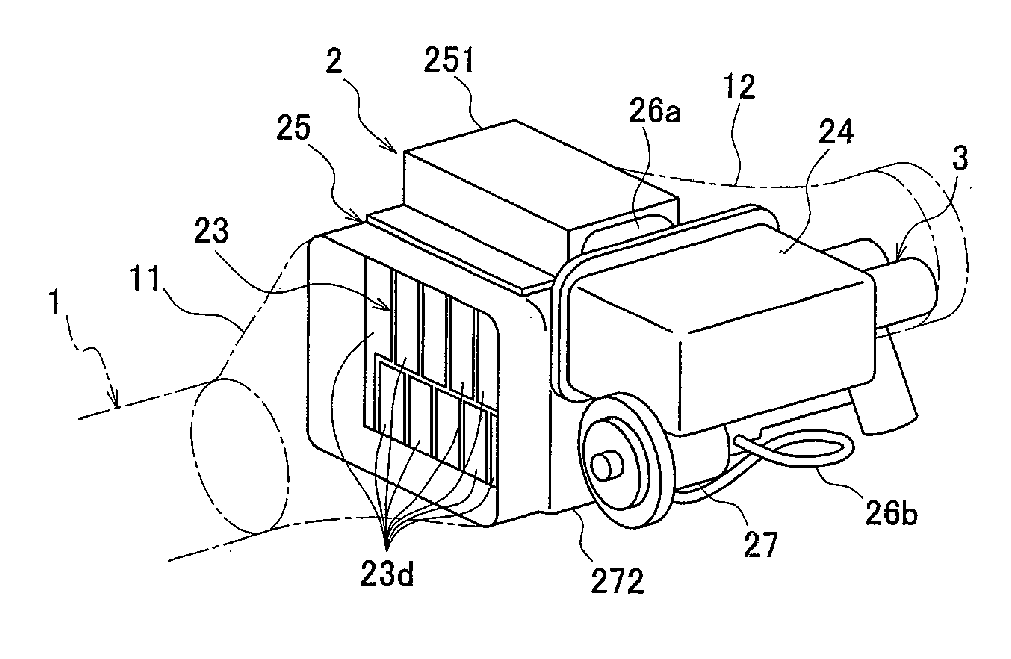
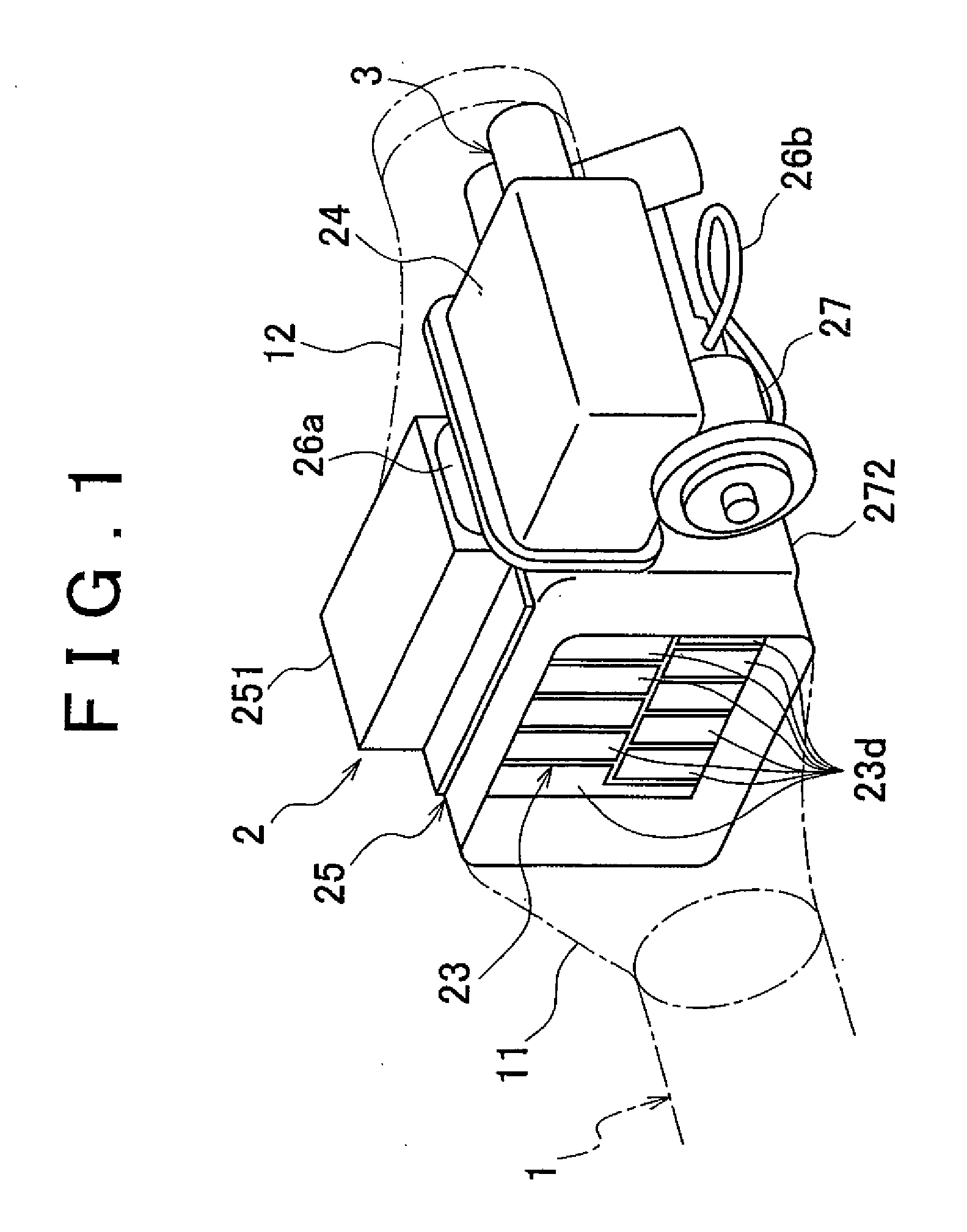
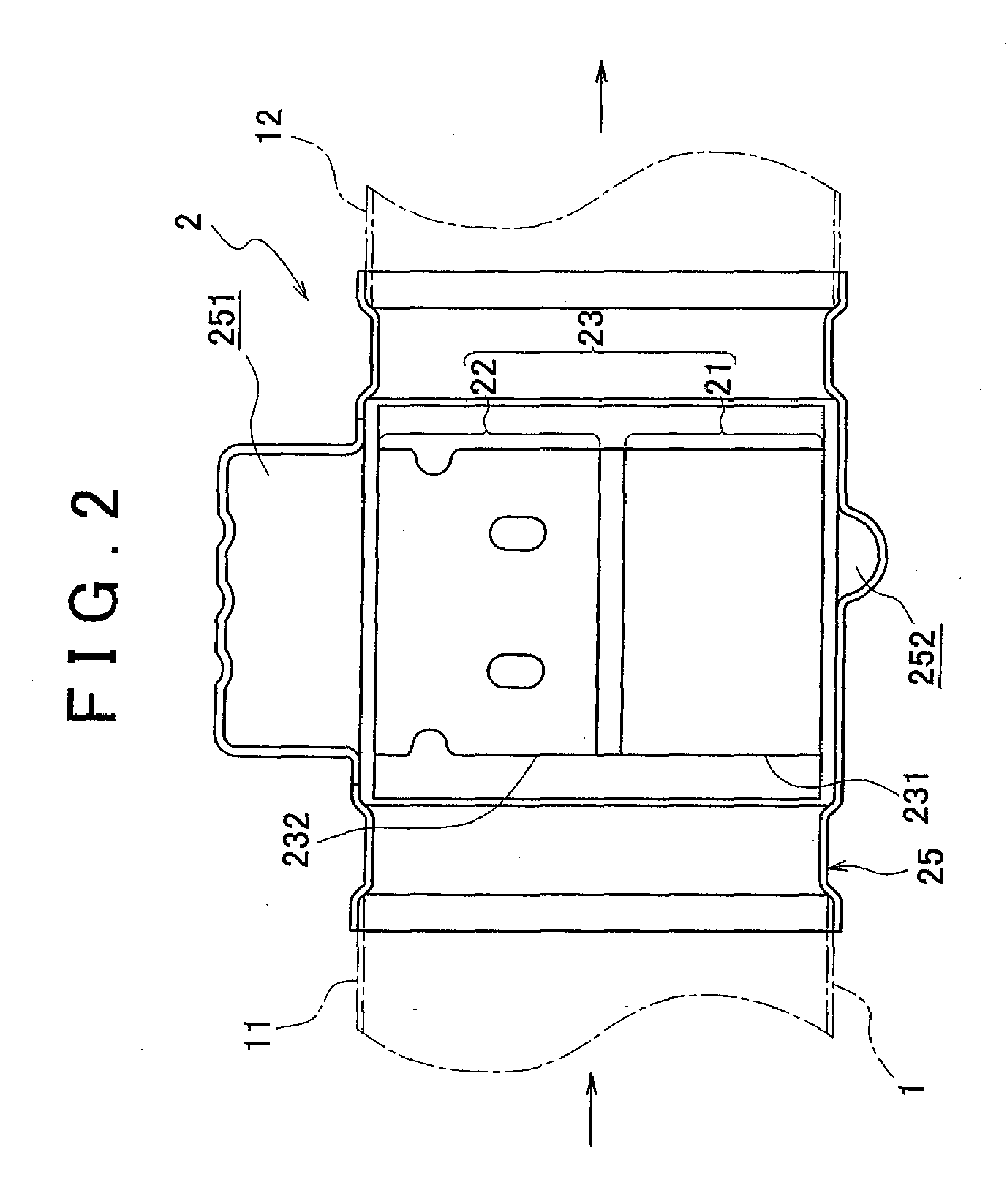
[0039]Thus, in the above-mentioned first embodiment, the heat pipe 23 causes the flow rate of pure water flowing through each of the heating unit side heat pipe portions 23a to be retarded in the merging portion 23c on the side of the evaporation unit 22 by the flow rate retardation means 4 provided with the merging portion 23c that merges pure water respectively heated by the seven heating unit side heat pipe portions 23a on the side of the heating unit 21 to the side of the evaporation unit 22. This is carried out to retard the flow rate of pure water merged from each of the heating unit side heat pipe portions 23a by retaining in the merging portion 23c having a large flow path cross-sectional area by causing pure water heated by each heating unit side heat pipe portion 23a to merge into the merging portion 23c on the side of the evaporation unit 22. Moreover, since the flow path cross-sectional area of the merging portion 23c is provided to be larger than the flow path cross-sec...

second embodiment

[0042]Next, an explanation is provided of the invention based on FIG. 4.

[0043]A different configuration is employed for the heat pipe in this second embodiment. Furthermore, other constituents with the exception of the heat pipe are the same as in the case of the above-mentioned first embodiment, like reference numerals are used to indicate like constituents, and a detailed explanation thereof is omitted.

[0044]Namely, in this second embodiment, a heat pipe 28 allows the flow of a working fluid in the form of pure water there through, and is housed within the evaporation side case 25 in the shape of a rectangular frame. A central portion of the evaporation side case 25 in which this heat pipe 28 is located is arranged so as to face an inside of the exhaust pipe 1. The heat pipe 28 is provided with a plurality of heating unit side heat pipe portions 28a on the side of the heating unit 21 (bottom of FIG. 4) that heats pure water with heat of exhaust gas, and a plurality of evaporation ...


PUM


Abstract

A heat pipe 23 has seven heating unit side heat pipe portions 23a on the side of a heating unit 21 for heating pure water using heat of exhaust gas discharged from an engine, six evaporation unit side heat pipe portions 23b on the side of an evaporation unit 22 for evaporating the pure water heated by each heating unit side heat pipe portion 23a using heat of exhaust gas, and flow rate retardation means 4 for retarding the flow rate of the pure water flowing in the evaporation unit side heat pipe portions. The flow rate retardation means 4 is provided with a merging portion 23c that merges the pure water heated by each heating unit side heat pipe portion, on the evaporation unit side, and whose a flow path cross-sectional area is set to be larger than that of each heating unit side heat pipe portion 23a.

Description

BACKGROUND OF THE INVENTION[0001]1. Field of the Invention[0002]The invention relates to a heat pipe used in a vehicle such as an automobile, an exhaust heat recoverer provided therewith.[0003]2. Description of the Related Art[0004]A conventional example of the related art uses the principle of a heat pipe to recover exhaust heat of exhaust gas discharged from an engine of a vehicle and use this exhaust heat to promote engine warming and the like.[0005]In addition, a loop heat pipe heat exchanger has been proposed that utilizes the principle of a heat pipe (see, for example, Japanese Patent Application Publication No. 4-45393 (JP-A-4-45393)). This heat exchanger has a closed circulation path that forms a closed loop, a working fluid charged into the circulation path enabling evaporation and condensation, an evaporation unit arranged in the circulation path that evaporates the working fluid by introducing heat from the outside, and a condensation unit arranged at a higher location th...

Claims


Application Information

Patent Timeline
IPC IPC(8): F28D15/04
CPCF01N5/02F28D15/0266Y02T10/16F28F13/06F28D21/0003Y02T10/12
Inventor MABUCHI, TOMOKITOI, MASAOTOKI, HIROYUKI
Owner TOYOTA JIDOSHA KK
Why Eureka
Try Eureka