Industrial continuous cracking device of plastics
a continuous cracking and plastic technology, applied in the direction of mechanical conveying coke ovens, products, educts, etc., can solve the problems of complex equipment structure, and achieve the effects of low running cost, simple configuration, and small volum
- Summary
- Abstract
- Description
- Claims
- Application Information
AI Technical Summary
Benefits of technology
Problems solved by technology
Method used
Image
Examples
example 1
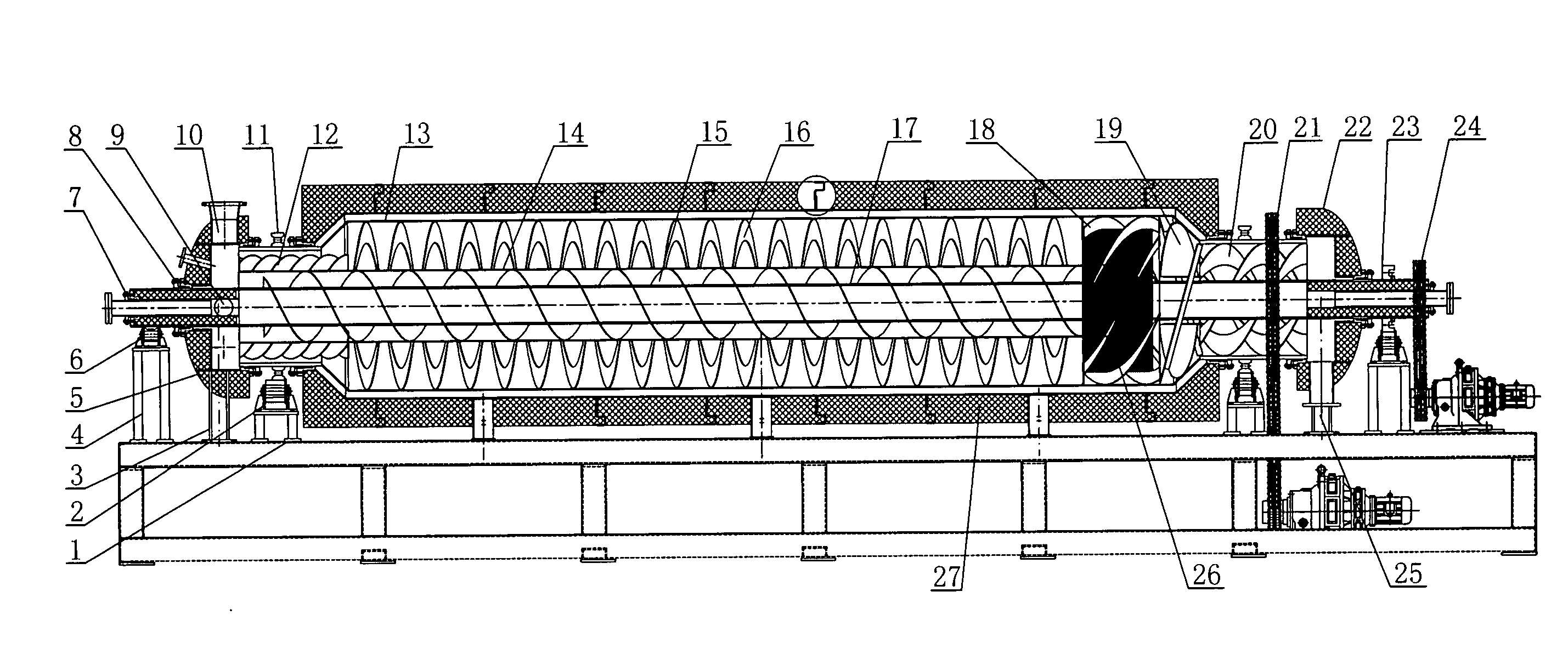
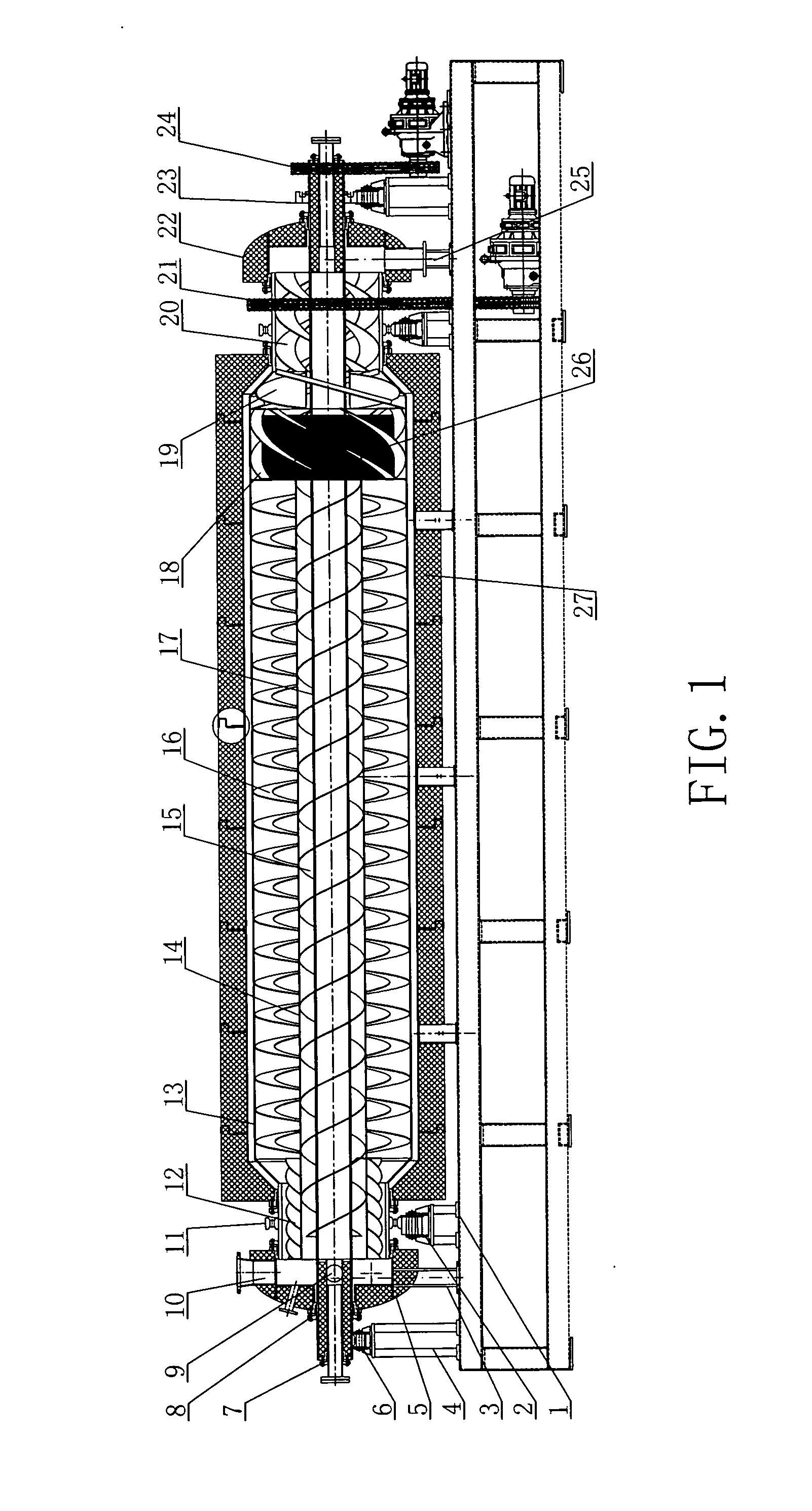
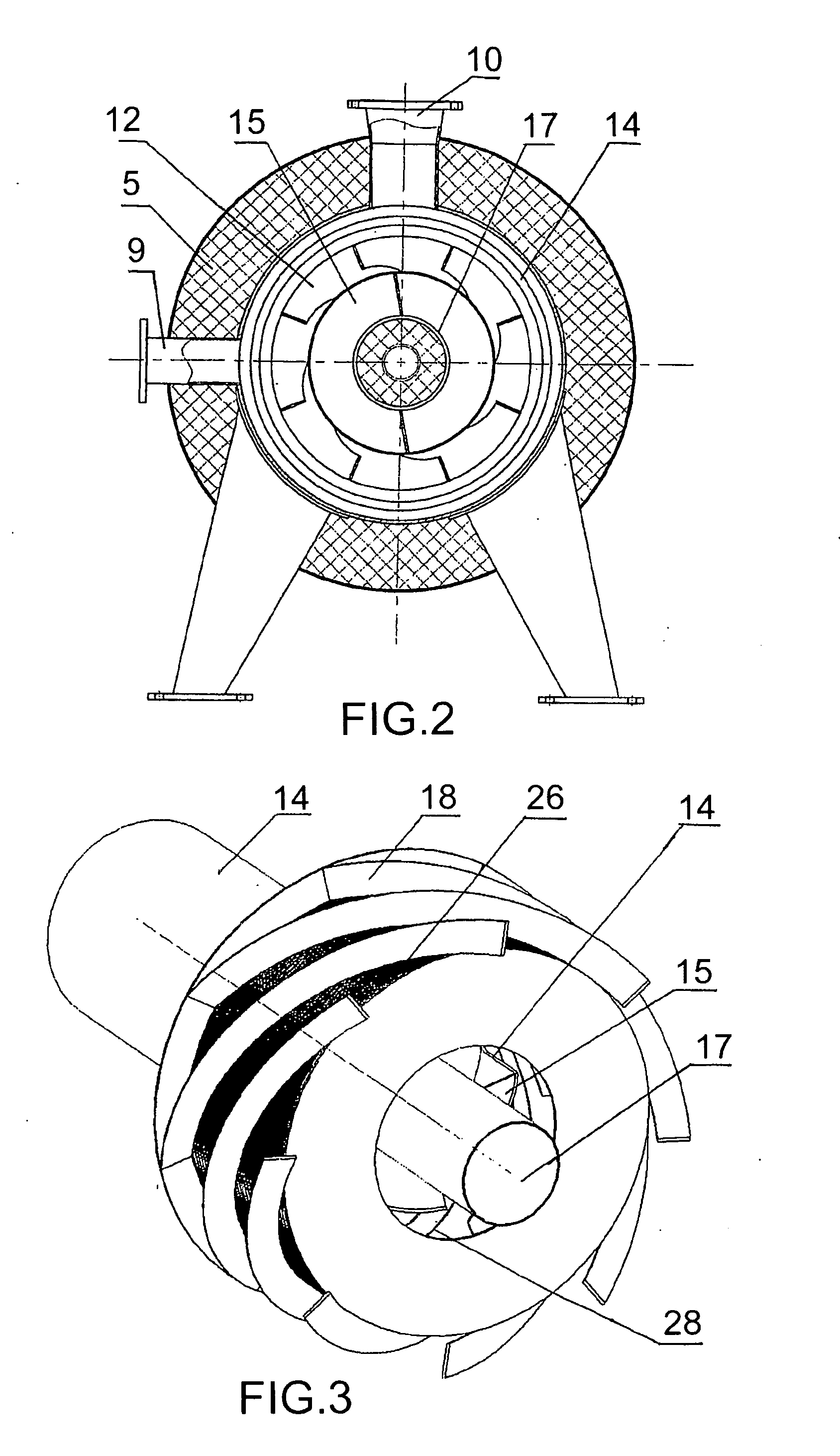
[0023]This example includes the outer cylinder and the internal cylinder, and the two ends of the internal cylinder are communicated with the outer cylinder. The heat mechanism is fixed in the outer cylinder, and the inner wall of the outer cylinder is set with helical ribbon. Inside the internal cylinder is fixed the transportation mechanism whose feeding direction is contrary to that of the outer cylinder. Furthermore, this transportation mechanism adopts the screw form. The liftingsing mechanism is set at the inlet of the internal cylinder, and it can transport the solid state heat carrier from the outer cylinder into the internal cylinder. The screening mechanism used for separating the solid state heat carrier and the solid product produced in cracking, is set in the outer cylinder. What's more, the oil-gas's outlet and the solid product's outlet corresponding with the screening mechanism are set on the outer cylinder.
example 2
[0024]This example includes the outer cylinder and the internal cylinder, and the two ends of the internal cylinder are communicated with the outer cylinder. The heat mechanism is fixed in the outer cylinder, and the inner wall of the outer cylinder is set with helical ribbon. The heat mechanism is fixed on the internal cylinder's outer wall. Inside the internal cylinder is fixed the transportation mechanism whose feeding direction is contrary to that of the outer cylinder. Furthermore, this transportation mechanism adopts the screw form. The lifting mechanism is set at the inlet of the internal cylinder, and it can transport the solid state heat carrier from the outer cylinder into the internal cylinder. The screening mechanism used for separating the solid state heat carrier and the solid product produced in cracking, is set in the outer cylinder. What's more, the oil-gas's outlet and the solid product's outlet corresponding with the screening mechanism are set on the outer cylind...
example 3
[0025]This example includes the outer cylinder and the internal cylinder, and the two ends of the internal cylinder are communicated with the outer cylinder. The heat mechanism is fixed in the outer cylinder, and the inner wall of the outer cylinder is set with helical ribbon. Inside the internal cylinder is fixed the transportation mechanism whose feeding direction is contrary to that of the outer cylinder. Furthermore, this transportation mechanism is the helical ribbon, which is fixed on the internal cylinder inner wall. The lifting mechanism is set at the inlet of the internal cylinder, and it can transport the solid state heat carrier from the outer cylinder into the internal cylinder. The screening mechanism used for separating the solid state heat carrier and the solid product produced in cracking, is set in the outer cylinder. What's more, the oil-gas's outlet and the solid product's outlet corresponding with the screening mechanism are set on the outer cylinder.
PUM
 Abstract
Description
Claims
Application Information
 - R&D
- Intellectual Property
- Life Sciences
- Materials
- Tech Scout
- Unparalleled Data Quality
- Higher Quality Content
- 60% Fewer Hallucinations
Browse by: Latest US Patents, China's latest patents, Technical Efficacy Thesaurus, Application Domain, Technology Topic, Popular Technical Reports.
© 2025 PatSnap. All rights reserved.Legal|Privacy policy|Modern Slavery Act Transparency Statement|Sitemap|About US| Contact US: help@patsnap.com


