Mass analysis method and mass analysis system

a mass analysis and mass technology, applied in the field of mass analysis methods and mass analysis systems, can solve the problems of deteriorating measurement throughput, requiring a considerable length of measurement, and the inability to directly convert time-of-flight spectrum to mass spectrum, so as to achieve high mass resolution and improve measurement throughput.

Active Publication Date: 2010-11-11
SHIMADZU CORP
View PDF2 Cites 6 Cited by
  • Summary
  • Abstract
  • Description
  • Claims
  • Application Information

AI Technical Summary

Benefits of technology

[0035]By the mass analysis method and mass analysis system according to the first and second aspects of the present invention, performing a measurement in the no-passing mode one time followed by a measurement in the loop-turn mode one time, is, in most cases, sufficient to identify the masses of the ions corresponding to the peaks appearing on a time-of-flight spectrum obtained in the loop-turn mode. In the loop-turn mode mass analysis, the passing of ions having different masses may occur, which consequently makes it possible to identify the mass of the ions over a much broader mass range yet with higher mass resolutions than ever before. Since it is unnecessary to repeat a measurement with a limited mass range, the entire measurement requires a shorter period of time. Thus, the measurement throughput is improved. Furthermore, it is unnecessary to perform complex calculations, such as the calculation of a multiple correlation function.

Problems solved by technology

However, it has a drawback due to the fact that the flight path of the ions is a closed orbit.
In this case, it is impossible to uniquely relate the mass of the ions to their flight distance, so that the time-of-flight spectrum cannot be directly converted to a mass spectrum.
Such a measurement requires a considerable length of time and seriously deteriorates the measurement throughput.
However, if there is only a small number of time-of-flight spectrums to be combined, this method may artificially create a false peak that does not really exist.
Thus, a measurement by this method also inevitably requires a long period of time.
Furthermore, this method is also inefficient in that the calculation of the multiple correlation function generally involves complex operations that consume a considerable amount of time.

Method used


Image

  • Mass analysis method and mass analysis system
  • Mass analysis method and mass analysis system
  • Mass analysis method and mass analysis system

Examples


example

[0084]To verify the effectiveness of the technique used in the previously described mass analysis method according to the present invention, a simulation was performed as follows.

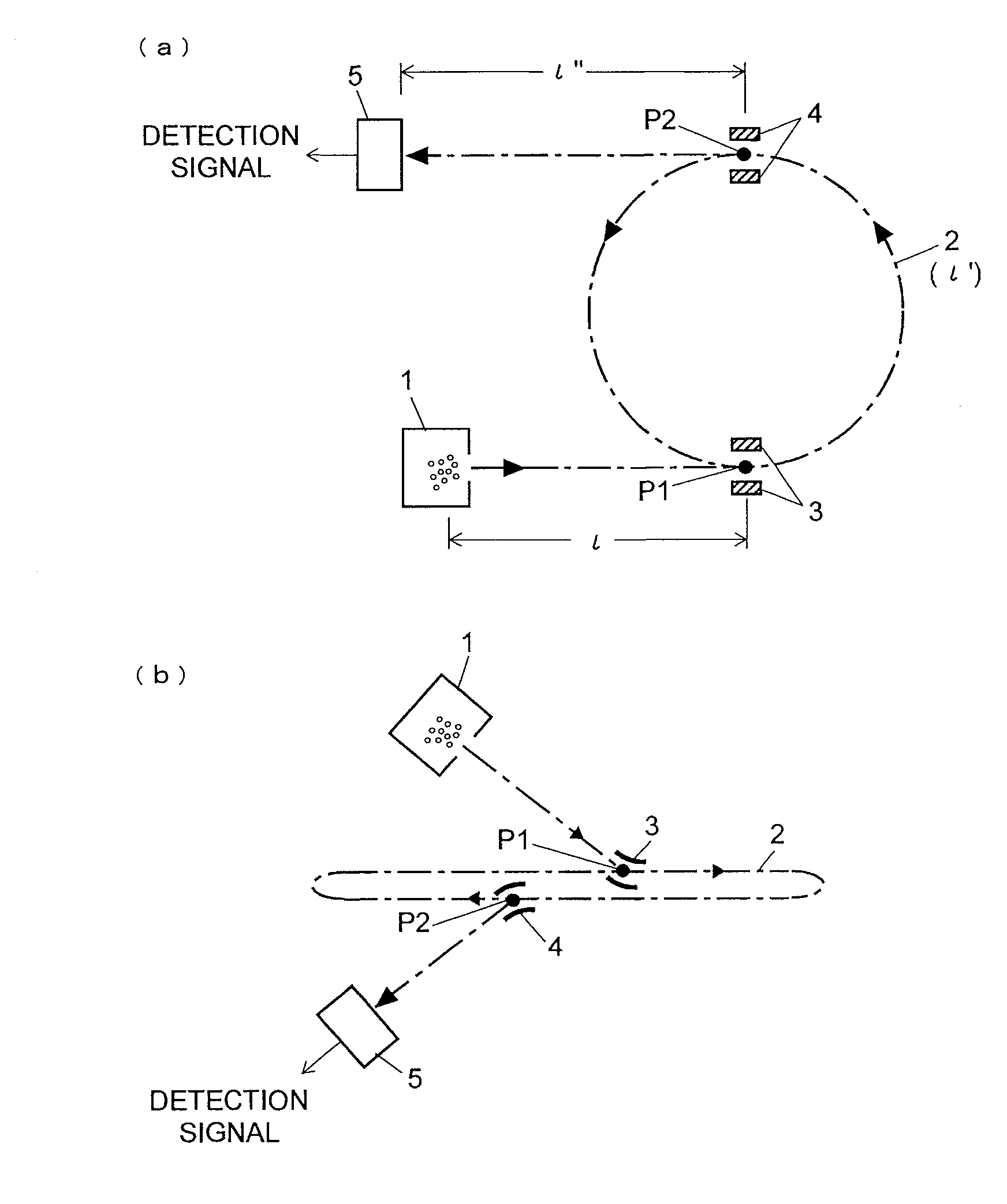
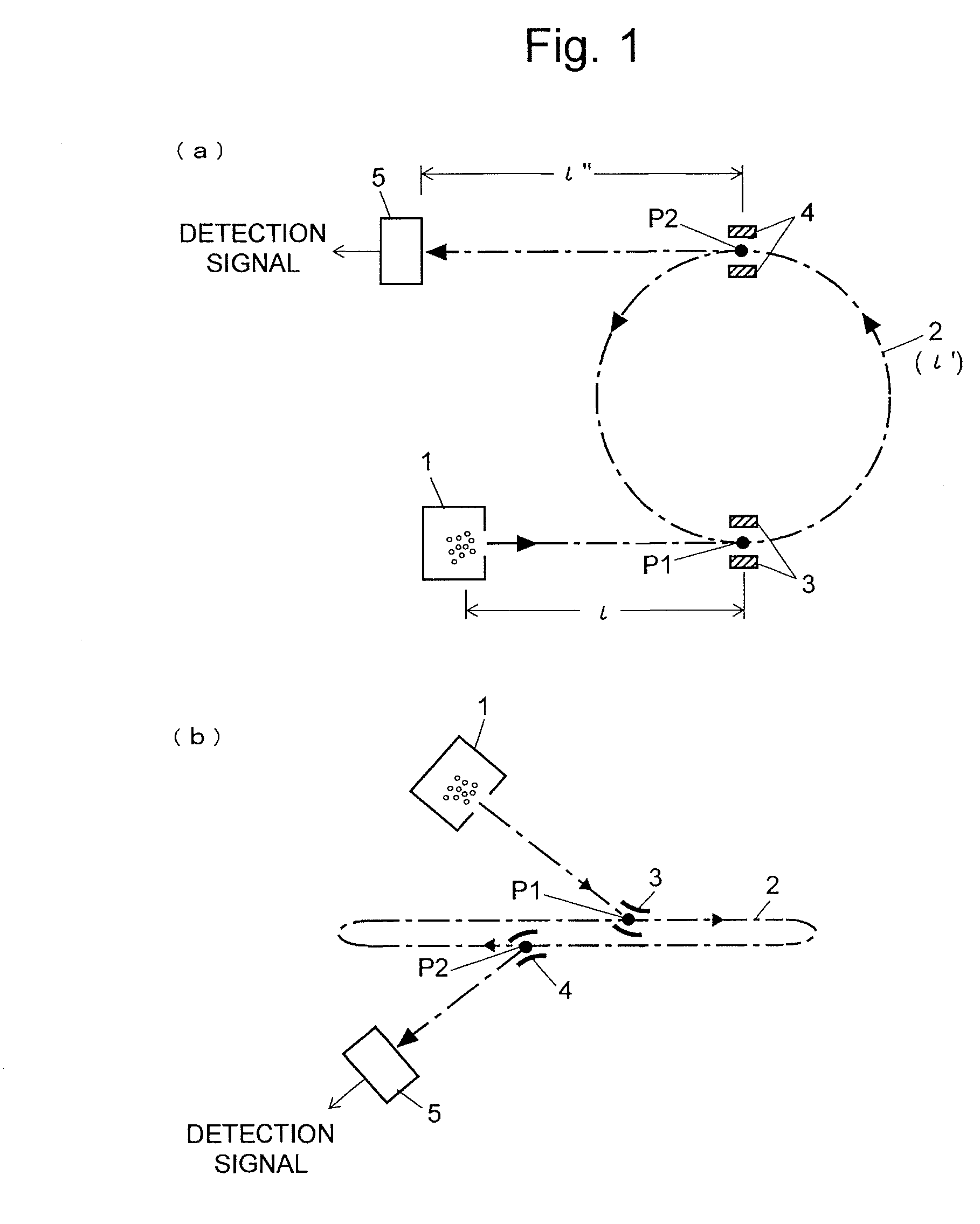
[0085]The simulation assumed that the system had a configuration shown in FIG. 1(a), with ι=ι′ι″=0.5 [m] and L=1.0 [m]. The ion-accelerating voltage was 10 kV. The sampling rate for signal observation was 1 GS per second. The ions to be measured were simulated by generating random numbers, which represented the number of existing ion packets and the mass and intensity of each ion. A restriction due to the structure of the ion optical system was imposed on the mass range for generating the ions, as will be hereinafter described.

[0086]While introducing ions into the loop orbit 2, the injection switch 3, which is used for guiding ions from the ion source 1 into the loop orbit 2, is supplied with a voltage to deflect the ions. While the ions are flying through the loop orbit 2, this voltage must be set to zero ...


PUM


Abstract

A measurement is performed in a no-passing mode, in which ions having different masses are prevented from making a complete turn through a loop orbit, to obtain a time-of-flight spectrum without the passing of ions having different masses (S1 and S2). From the time of flight and other information of the peaks appearing on the time-of-flight spectrum (S3), the number of turns and the time of flight in the loop-turn mode are predicted. Based on this prediction, a set of segments are defined on a time-of-flight spectrum in the loop-turn mode. The time widths of those segments are determined taking into account the spreads of the time widths of the aforementioned peaks. Since the number of turns is unique within each segment, the numbers of turns and the masses of the peaks can be uniquely determined as long as none of the segments overlap each other. Accordingly, it is determined whether there is any overlapped portion in the segments defined on the time-of-flight spectrum in the loop-turn mode under provisionally predetermined conditions. When a condition under which no overlapping occurs has been found, the segment setting is fixed (S4-S6). As a result, the timing for switching an ejection switch, which is used for ejecting ions from the loop orbit, is also determined. Based on this timing, a measurement in the loop-turn mode is performed (S7).

Description

TECHNICAL FIELD[0001]The present invention relates to a mass analysis method and mass analysis system, and more specifically to a method and system for a multi-turn time-of-flight mass analysis using an ion optical system that makes ions fly along a closed orbit.BACKGROUND ART[0002]Time-of-flight mass analyzers is a type of device that performs mass analyses by measuring the time of flight required for each ion to travel a specific distance and converting the time of flight to a mass. This analysis is based on the principle that ions accelerated by a specific amount of energy will fly at different speeds that correspond to their mass. Therefore, to improve the mass resolution, it is effective to provide the longest possible flight distance. For this purpose, multi-turn time-of-flight mass spectrometers have been developed and have successfully achieved high levels of mass resolution (for example, refer to Patent Documents 1 to 3 and Non-Patent Document 1). This type of mass spectrom...

Claims


Application Information

Patent Timeline
Patent Type & Authority Applications(United States)
IPC IPC(8): H01J49/40
CPCH01J49/408
Inventor NISHIGUCHI, MASARUKAJIHARA, SHIGEKI
Owner SHIMADZU CORP
Why Eureka
Try Eureka