Multi-panel color projector using multiple light-emitting diodes as light sources

a color projector and light source technology, applied in the field of color light projection, can solve the problems of relatively high cost of the relatively bulky projector of fig. 1, etc., and achieve the effects of high accuracy digital color modulation, high efficiency of operation, and low component count of inventive projectors

Inactive Publication Date: 2010-11-11
VIDEO DISPLAY CORP
View PDF7 Cites 10 Cited by
  • Summary
  • Abstract
  • Description
  • Claims
  • Application Information

AI Technical Summary

Benefits of technology

[0029]In short, the use of LEDs as light sources in the projectors of the invention enables a projector designer to take advantage of high-brightness LEDs that are now commercially available. The invention also normally takes advantage of the highly accurate digital color modulation provided by DMDs. The average optical path length in the inventive projectors is likewise typically comparatively low, thereby leading to highly efficient operation. The component count in the inventive projectors is comparatively low. Also, the projectors are of comparatively small size.
[0030]All light modulation i...

Problems solved by technology

In addition, prisms 28, 30, 32, 34, and 36 occupy considerable space and cause the projector of FIG. 1 to be relatively bulky.
As a result, the projector of FIG. 1 is also r...

Method used


Image

  • Multi-panel color projector using multiple light-emitting diodes as light sources
  • Multi-panel color projector using multiple light-emitting diodes as light sources
  • Multi-panel color projector using multiple light-emitting diodes as light sources

Examples


Embodiment Construction

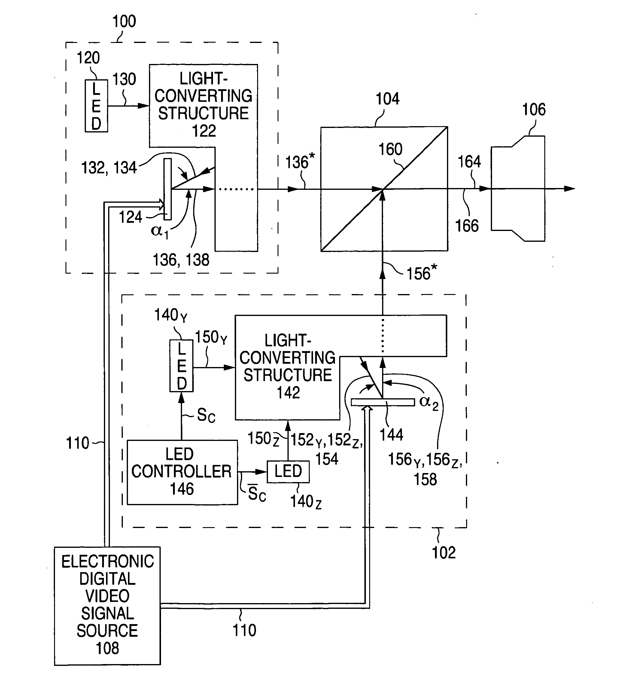
[0040]FIG. 3 illustrates a general two-panel DLP LED-source color light projector configured according to the invention. The two-panel projector of FIG. 3 consists of a one-LED first optical assembly 100, a two-LED second optical assembly 102, a beam combiner 104, a projection lens device 106, and an electronic digital video signal source 108 that provides an input electronic digital video signal 110 at a video update frequency fFR.

[0041]First optical assembly 100 is formed with a first color LED 120, first light-converting structure 122, and a first offset-angle reflective digital light modulating device 124. LED 120 emits light of a first selected color, referred to here as first selected color X, to produce a first intermediate beam 130 of light of first selected color X. Light-converting structure 122 converts first intermediate color beam 130 into a second intermediate beam 132 of light of first selected color X. As described below in connection with FIG. 4, the light-conversio...


PUM


Abstract

A color light projector utilizes color light-emitting diodes (120, 140Y, and 140Z or 320X, 320Y, and 320Z) as light sources. Digital light modulators (124 and 144 or 324X, 324Y, and 324Z), typically digital micromirror devices, perform reflective color light modulation. In one implementation, light of three or more colors is modulated efficiently with only two modulators so that the component count and cost are low. In another implementation, each of three different colors is modulated with a separate modulator. A beam combiner (104 or 304) combines the digitally modulated beams (136* and 156* or 336X*, 336Y*, and 336Z*) of color light to produce a composite beam (166 or 346) of the different colors. A projection lens device (106) projects the composite color beam.

Description

FIELD OF USE[0001]This invention relates to color light projection and, in particular, to color light projection typically using digital light-processing (“DLP”) technology.BACKGROUND ART[0002]A key component of a DLP color projector is a semiconductor chip, commonly referred to as a digital micromirror device (“DMD”), in which a microelectromechanical system is employed as a light modulation panel to achieve highly accurate color light modulation. The use of DMDs as light modulation panels enables DLP color projectors to have high resolution and high contrast. The image displayed by a DLP projector is normally bright and seamless.[0003]Referring to FIG. 1, it illustrates a conventional three-panel (or three-chip) DLP lamp-source color projector as described in Hornbeck, “Digital Light Processing™ for High-Brightness, High-Resolution Applications”, 21st, The VXN Network, http: / / www.vxm.com, Summer 1998, 21pp. The DLP projector of FIG. 1 consists of lamp 20, curved light reflector 22...

Claims


Application Information

Patent Timeline
IPC IPC(8): H04N5/74G03B21/00
CPCG03B33/12H04N9/3111G03B21/208H04N9/3197G03B21/2033H04N9/3164
Inventor LI, HAIZHANG
Owner VIDEO DISPLAY CORP
Why Eureka
Try Eureka