Illumination system and illumination control method

a technology of illumination control and illumination system, which is applied in the field of light source, can solve the problems of affecting the color accuracy of images projected onto the viewing screen, wasting substantial amount of light energy provided by a light source, and affecting the contrast of projected images, so as to improve the efficiency of light energy use and improve the color accuracy of images

Active Publication Date: 2010-11-11
CORETRONIC
View PDF10 Cites 48 Cited by
  • Summary
  • Abstract
  • Description
  • Claims
  • Application Information

AI Technical Summary

Benefits of technology

[0010]The present invention provides an illumination system that may substantially improve the color accuracy of images projected by a projection apparatus, along with substantially better efficiency in using light energy.
[0011]The present invention provides an illumination system that may adjust the brightness and the color quality of images projected by the projection apparatus according to a plurality of distinct requirements from different users, along with substantially better efficiency in using light energy.
[0012]The present invention provides an illumination control method that substantially improves the color accuracy of images projected by the projection apparatus, along with substantially better efficiency in using light energy.
[0017]In summary, in the illumination systems and the illumination control method of the embodiments of the present invention may have at least one of the following advantages: when the boundary of any two adjacent light color modulating units move into the illumination region of the light beam, the light source module is switched to an off-state. Therefore, a substantial improvement in the color accuracy of the images projected by the projection apparatus is provided, and the light energy provided by the light source module is used efficiently. In the illumination system and illumination control method of the embodiments of the present invention, when the illumination region of the light beam falls within a region formed by the white light color modulating unit, a turn-on time of the light emitting device may be adjusted. Therefore, adjustment of the brightness and color quality of the projected images from the projection apparatus is provided according to different requirements of users, and the light energy provided by the light source module is used efficiently.

Problems solved by technology

Consequently, incorrect colored light beams are transmitted to the light valve and thereby affecting the color accuracy of the images projected onto a viewing screen.
Although shutting down the SLM during the spoke time may help to improve the accuracy of the colors displayed on the viewing screen, dark images may be not dark enough, and thus the contrast of the projected images may deteriorate substantially since the light source is still in operation during the shut-off of the SLM.
Moreover, a substantial amount of light energy provided by a light source is wasted due to maintaining the on-state of the light source when shutting off the SLM.
Although doing so saves energy, neither of the disclosures provides methods for substantially improving the accuracy of the displayed colors during the spoke time.

Method used


Image

  • Illumination system and illumination control method
  • Illumination system and illumination control method
  • Illumination system and illumination control method

Examples


Embodiment Construction

[0029]It is to be understood that other embodiment may be utilized and structural changes may be made without departing from the scope of the present invention. Also, it is to be understood that the phraseology and terminology used herein are for the purpose of description and should not be regarded as limiting. The use of “including,”“comprising,” or “having” and variations thereof herein is meant to encompass the items listed thereafter and equivalents thereof as well as additional items. Unless limited otherwise, the terms “connected,”“coupled,” and “mounted,” and variations thereof herein are used broadly and encompass direct and indirect connections, couplings, and mountings.

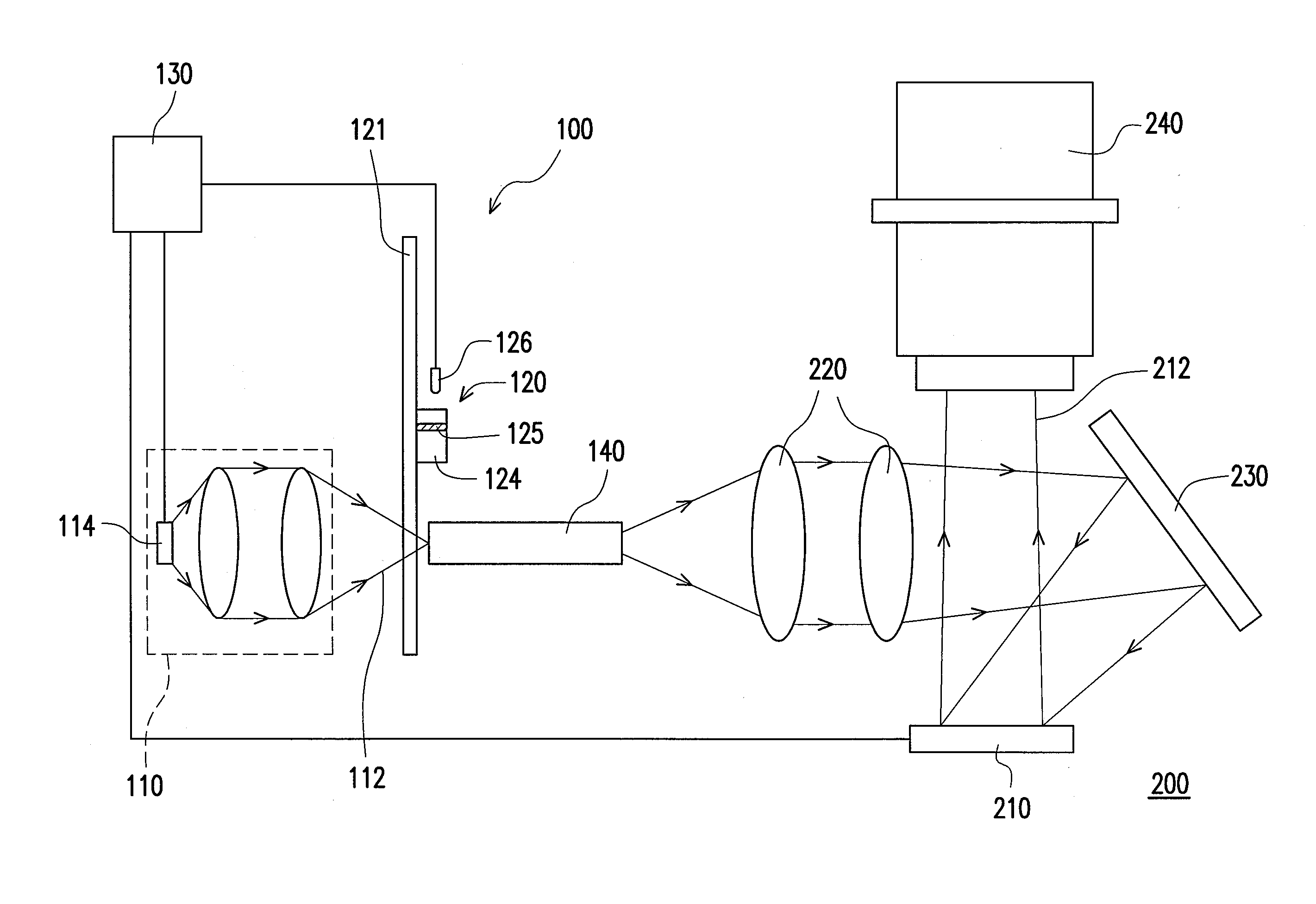
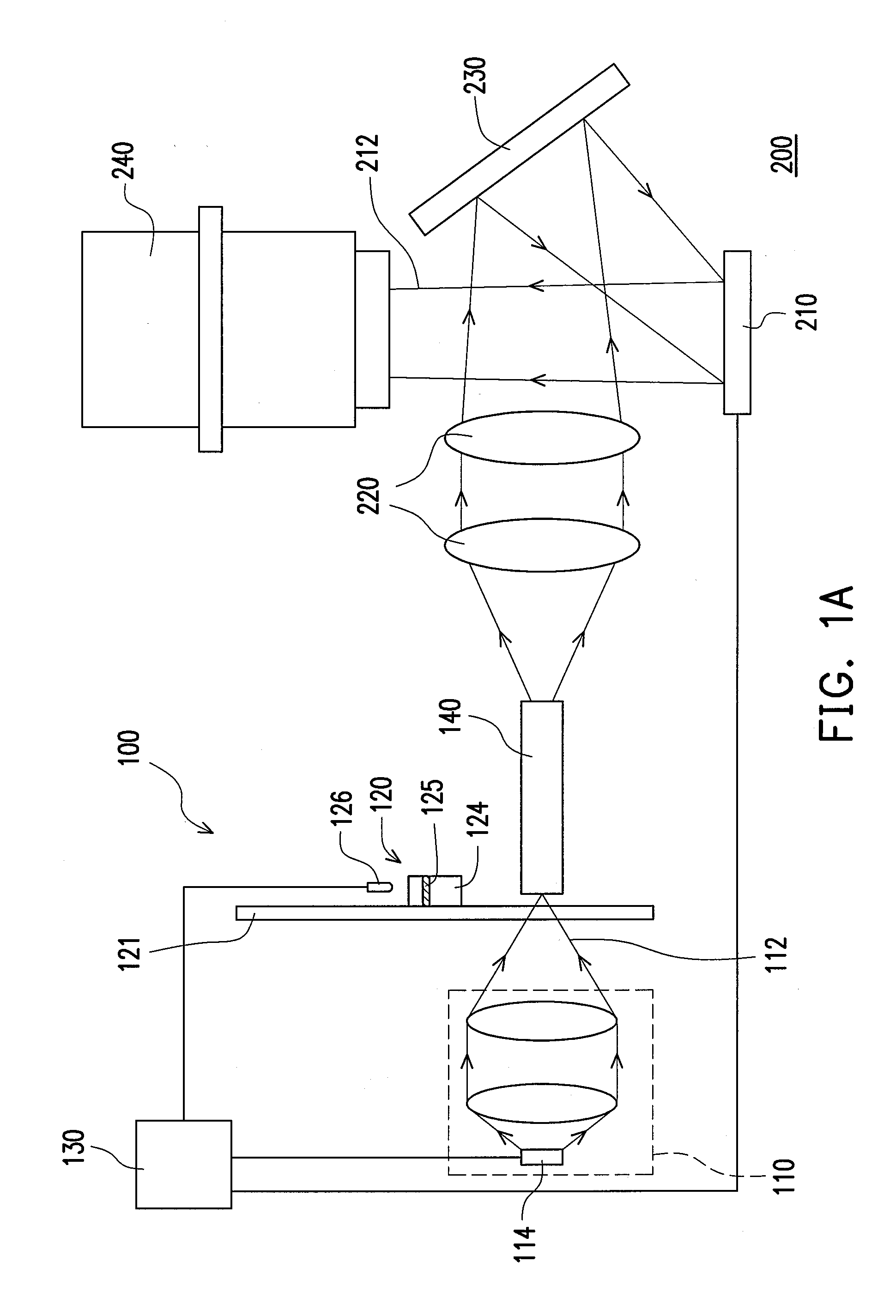
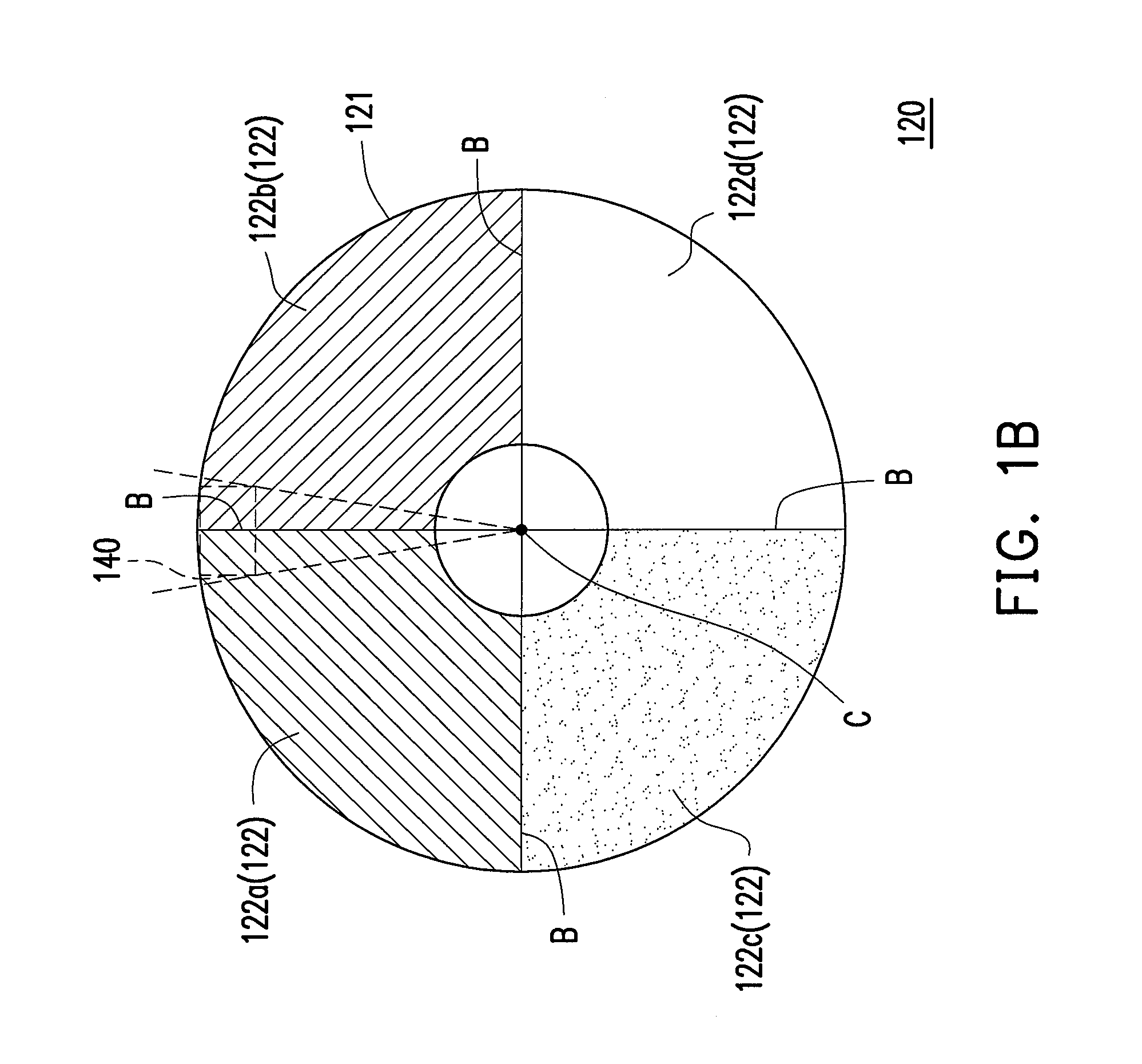
[0030]FIG. 1A is a schematic view illustrating the structure of an illumination system adapted in a projection apparatus in accordance with one embodiment of the present invention. FIG. 1B is a front view of a light color modulating module depicted in FIG. 1A. Referring toFIG. 1A and FIG. 1B, an illuminatio...


PUM


Abstract

An illumination system adapted to a projection apparatus is provided, including a light source module, a light color modulating module, and a control unit. The light color modulating module has a plurality of light color modulating units and is disposed in a transmission path of a light beam. The light color modulating module is capable of moving so that the light color modulating units move into the illumination region of the light beam. When the control unit determines that a boundary of any two adjacent light color modulating units has moved into the illumination region of the light beam, the control unit switches the light source module to an off-state. When the boundary of any two adjacent light color modulating units has moved away from the illumination region of the light beam, the control unit switches the light source module to an on-state. An illumination control method is also provided.

Description

CROSS-REFERENCE TO RELATED APPLICATION[0001]This application claims the priority benefit of Taiwan application serial no. 98115524, filed on May 11, 2009. The entirety of the above-mentioned patent application is hereby incorporated by reference herein and made a part of specification.BACKGROUND OF THE INVENTION[0002]1. Field of the Invention[0003]The present invention generally relates to a light source and a method of controlling the same. More specifically, the invention relates to an illumination system adapted to a projection apparatus and an illumination control method.[0004]2. Description of Related Art[0005]Conventionally, a projection apparatus provides color images with an illumination system sequentially emitting a red light beam, a green light beam, and a blue light beam to a light valve of the projection apparatus. This allows the projection apparatus to sequentially project red, green, and blue images onto a viewing screen. When red, green, and blue images appear rapid...

Claims


Application Information

Patent Timeline
Patent Type & Authority Applications(United States)
IPC IPC(8): G03B21/14G03B21/20
CPCH04N9/3114H04N9/3155G03B33/08G03B21/206G03B21/204
Inventor WANG, SZE-KELIU, CHIN-KU
Owner CORETRONIC
Why Eureka
Try Eureka