
Microscope system

a microscope and lens technology, applied in the field of microscope systems, can solve the problems of icsi viewing extremely difficult, significant interference of immersion liquid with the workability of ivf, etc., and achieve the effect of rapid and accurate, satisfactory workability

Active Publication Date: 2010-11-11
NIKON CORP
View PDF4 Cites 4 Cited by
  • Summary
  • Abstract
  • Description
  • Claims
  • Application Information

AI Technical Summary

Benefits of technology

[0010]As described above, according to the present invention, a microscope system suitable for micro-insemination can be provided whereby the sequence of operations in micro-insemination can be rapidly and accurately performed with satisfactory workability while the appropriate resolving power is maintained.

Problems solved by technology

As a result, in the conventional microscope system, an immersion-type lens is used as a high-magnification objective, and a dry-type lens is used as a medium-low-magnification objective, and during the switch to the dry-type medium-low-magnification objective for ICSI viewing after IMSI viewing through the immersion-type high-magnification objective, the immersion liquid significantly interferes with the workability of IVF.
In this system, however, the viscosity of the immersion liquid causes the sample (usually a dish) to move when immersion objectives are used exchangeably, the sperm selected using the high-magnification objective may move out of view, and bubbles and the like are prone to be introduced into the immersion liquid.
These problems can make ICSI viewing extremely difficult after the objectives are exchanged.

Method used


Image

  • Microscope system
  • Microscope system
  • Microscope system

Examples


examples

[0064]Examples of the second objective (dry-type high-magnification objective) according to the present embodiment will be described.

first example

[0065]A first example will be described using FIG. 7, FIG. 8, and Table 1. FIG. 7 is a sectional view showing the lens structure of the second objective (dry-type high-magnification lens) according to the present example. As shown in FIG. 7, the microscope objective in the present example comprises, in order from the object, a positive meniscus lens L1 having a concave surface facing the object; a positive meniscus lens L2 having a concave surface facing the object; a cemented lens composed of a double-concave lens L3 and a double-convex lens L4; a cemented lens composed of a double-concave lens L5 and a double-convex lens L6; a cemented lens composed of a planoconcave lens L7 and a double-convex lens L8; a double-convex lens L9; a cemented lens composed of a negative meniscus lens L10 having a concave surface facing the object, a double-convex lens L11, and a negative meniscus lens L12 having a concave surface facing the object; a cemented lens composed of a double-convex lens L13 ...


PUM


Abstract

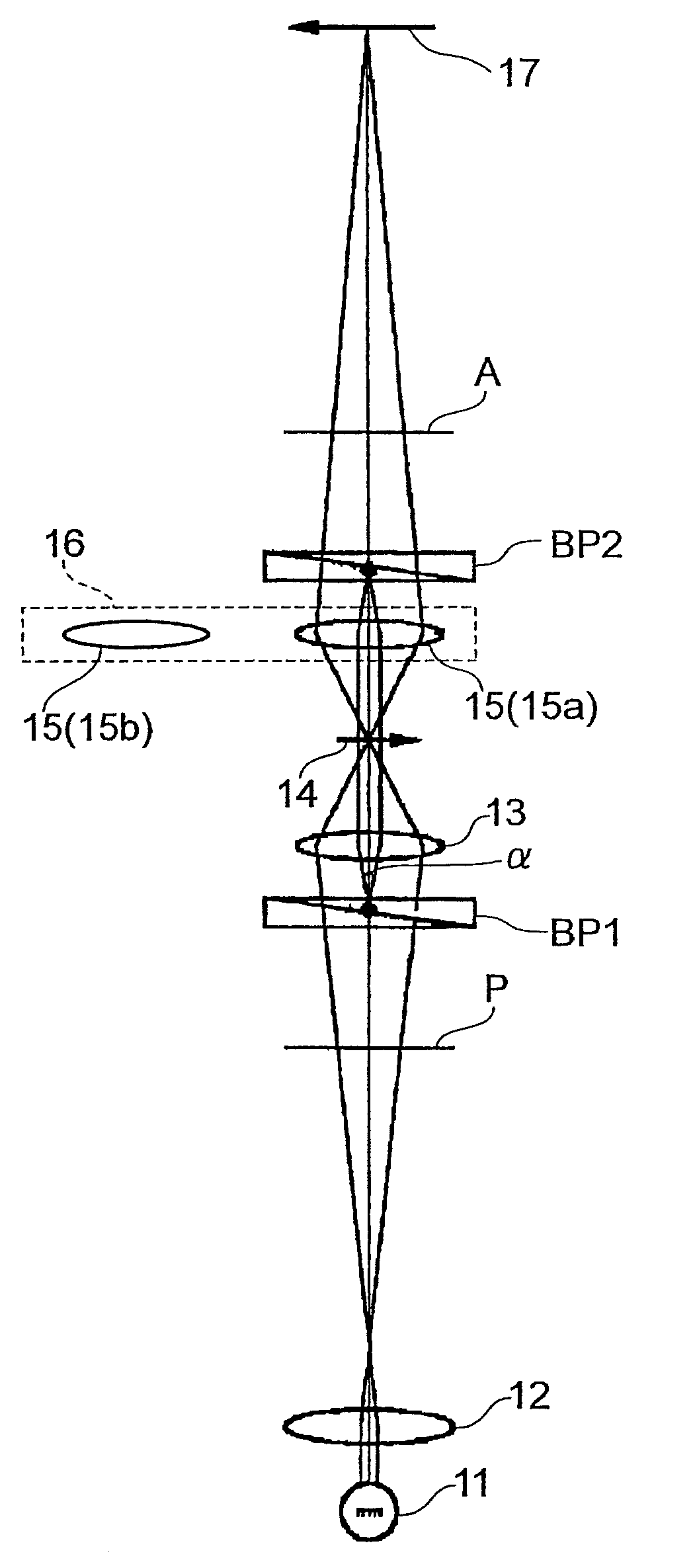
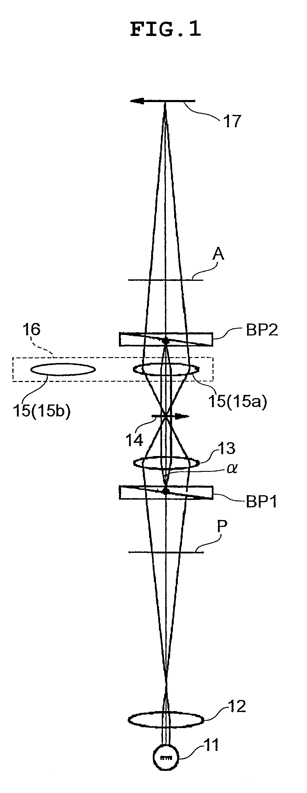
A microscope system is characterized in comprising a transmission illumination optical system having a light source (11) and a condenser lens (13); a first dry objective (15a) having a magnification of from 20 or higher to 40 or lower and capable of viewing by at least one of a differential interference viewing method and a modulation contrast viewing method; and a second dry objective (15b) having a magnification of from 60 or higher to 100 or lower and capable of viewing by a differential interference viewing method; the first objective (15a) and the second objective (15b) being exchangeable.

Description

[0001]This is a continuation of PCT International Application No.PCT / JP2009 / 050555, filed on Jan. 16, 2009, which is hereby incorporated by reference. This application also claims the benefit of Japanese Patent Application No. 2008-012823, filed in Japan on Jan. 23, 2008, which is hereby incorporated by reference.TECHNICAL FIELD[0002]The present invention relates to a microscope system for use with micro-insemination, the system being capable of viewing using a differential interference viewing method and a modulation contrast viewing method.TECHNICAL BACKGROUND[0003]At present, ICSI (intra-cytoplasmic sperm injection) is widely used as a micro-insemination method. In micro-insemination, a sperm is selected using a modulation contrast viewing method (see Patent Document 1, for example), and a sperm having satisfactory motility and morphology is injected into an ovum. However, recent advances in IVF (in-vitro fertilization) research have shown statistically that such factors as the p...

Claims


Application Information

Patent Timeline
IPC IPC(8): G02B21/06
CPCA61B19/5223A61B2019/5231Y10S359/90G02B21/02G02B21/14G02B13/22A61B90/20A61B2090/373
Inventor MATSUI, KUMIKOWATANABE, KATSUYA
Owner NIKON CORP
Learn More