Beam expansion with three-dimensional diffractive elements

Active Publication Date: 2010-11-11
MAGIC LEAP
View PDF8 Cites 213 Cited by
  • Summary
  • Abstract
  • Description
  • Claims
  • Application Information

AI Technical Summary

Problems solved by technology

Using separate diffraction elements makes manufacturing of such grating assembly difficult and requires a precise definition of the grating period (e.g., typically two different grating periods

Method used


Image

  • Beam expansion with three-dimensional diffractive elements
  • Beam expansion with three-dimensional diffractive elements
  • Beam expansion with three-dimensional diffractive elements

Examples


Embodiment Construction

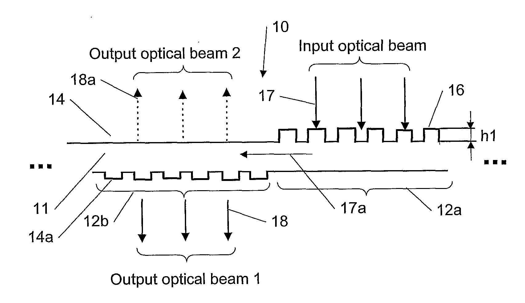
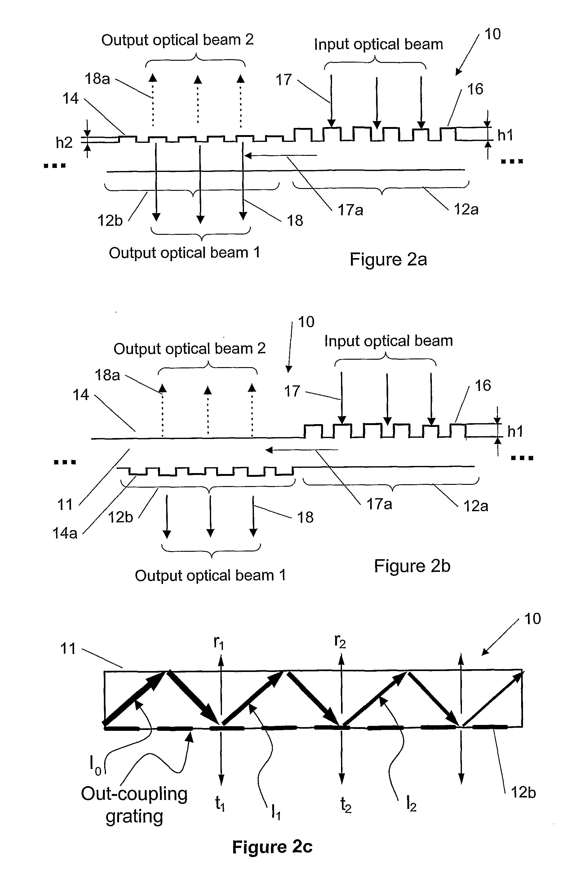
[0065]A new method and apparatus are presented for using a three-dimensional (3D) diffractive element (e.g., a 3D diffractive grating) for expanding in one or two dimensions the exit pupil of an optical beam in electronic devices. Various embodiments of the present invention can be applied, but are not limited, to forming images in virtual reality displays, to illuminating of displays (e.g., backlight illumination in liquid crystal displays) or keyboards, etc. The embodiments of the present invention can be applied to a broad optical spectral range of optical beams but most importantly to a visible part of the optical spectrum where the optical beams are called light beams.

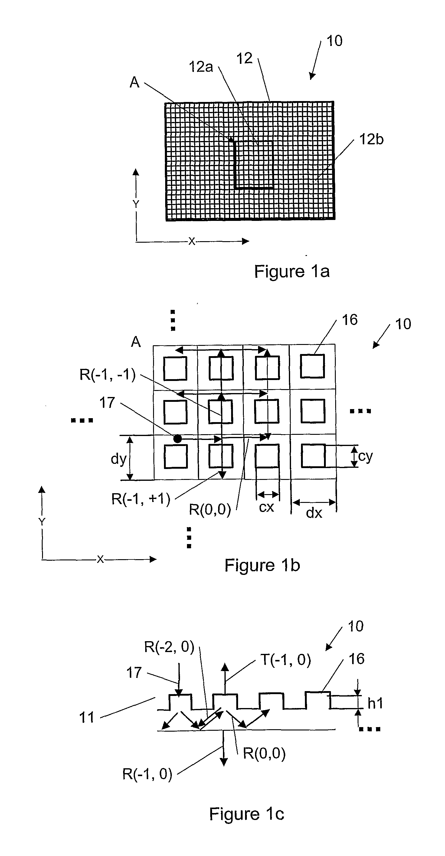
[0066]According to embodiments of the present invention, the optical device (e.g., the optical device can be a part of a virtual reality display of an electronic device) can comprise a substrate made of an optical material having a first surface and a second surface and a three-dimensional diffractive element (3D)...


PUM


Abstract

The specification and drawings present a new apparatus and method for using a three-dimensional (3D) diffractive element (e.g., a 3D diffractive grating) for expanding in one or two dimensions the exit pupil of an optical beam in electronic devices. Various embodiments of the present invention can be applied, but are not limited, to forming images in virtual reality displays, to illuminating of displays (e.g., backlight illumination in liquid crystal displays) or keyboards, etc.

Description

TECHNICAL FIELD[0001]The present invention relates generally to electronic devices and, more specifically, to a diffractive optics method that uses a three-dimensional (3D) diffractive element (e.g., a 3D diffraction grating) for expanding the exit pupil of an optical beam.BACKGROUND ART[0002]In a typical virtual display arrangement (e.g., see PCT patent application WO 99 / 52002 “Holographic Optical Devices” by Yaakov Amitai and Asher Friesem and U.S. Pat. No. 6,580,529 “Holographic Optical Devices” by Yaakov Amitai and Asher Friesem), the virtual image is typically formed by using several separate linear diffraction gratings. Using separate diffraction elements makes manufacturing of such grating assembly difficult and requires a precise definition of the grating period (e.g., typically two different grating periods are used) and an angle between the periodic lines. Furthermore, it requires a lot of space and the diffraction efficiency is usually dependent on polarization (e.g., str...

Claims


Application Information

Patent Timeline
IPC IPC(8): G02B27/42G02B30/00
CPCG02B5/18G02B6/12007G03H1/0408G02B27/0081G03H1/0244G02B6/124
Inventor LAAKKONEN, PASI
Owner MAGIC LEAP
Why Eureka
Try Eureka