Nuclear reactor

Active Publication Date: 2010-11-11
MITSUBISHI HEAVY IND LTD
View PDF8 Cites 7 Cited by
  • Summary
  • Abstract
  • Description
  • Claims
  • Application Information

AI Technical Summary

Benefits of technology

[0023]In a nuclear reactor according to claim 1, a core barrel is disposed in a pressure vessel that includes a coolant inlet nozzle and a coolant outlet nozzle, a core is disposed in the core barrel, a lower plenum is partitioned by the pressure vessel and a bottom portion of the core barrel, and a downcomer portion is partitioned by the pressure vessel and a side wall of the core barrel. The lower plenum includes a straightener member formed of a straightening ring in a ring shape and a plurality of straightening spokes radially arranged inside the straightening ring. When coolant introduced into the pressure vessel flows down the downcomer portion, reaches the lower plenum, reversed in the lower plenum, and flows upward, the flow of coolant is dispersed by the straightening ring and the straightening spokes, thereby preventing the generation of large vortices. Because the flow rate of the coolant supplied to the core is uniformly straightened in the radial direction and the circumferential direction of the core, it is possible to enhance heat exchange efficiency.
[0024]In a nuclear reactor according to claim 2, the straightening ring includes an upper ring and a lower ring, and is supported by a plurality of columns suspended from a lower core plate. The coolant that flows down the downcomer portion, reversed in the lower plenum, and flows upward, is dispersed by the columns in addition to the upper ring, the lower ring, and the straightening spokes, thereby preventing the generation of large vortices. Accordingly, the flow rate of the coolant supplied to the core is uniformly straightened in the radial direction and the circumferential direction of the core.
[0025]In a nuclear reactor according to claim 3, the straightening ring includes an outer ring and an inner ring, and is supported by a plurality of columns suspended from a lower core plate, and a plurality of straightening spokes is provided between the outer ring and the inner ring. The coolant that flows down the downcomer portion, reversed in the lower plenum, and flows upward, is dispersed by the columns in addition to the outer ring, the inner ring, and the straightening spokes, thereby preventing the generation of large vortices. Accordingly, the flow rate of the coolant supplied to the core is uniformly straightened in the radial direction and the circumferential direction of the core.
[0026]In a nuclear reactor according to claim 4, an intermediate ring is arranged between the outer ring and the inner ring, and the intermediate ring intersects with the straightening spokes. The coolant that flows down the downcomer portion, reversed in the lower plenum, and flows upward, is dispersed by the intermediate ring in addition to the outer ring, the inner ring, and the straightening spokes, thereby preventing the generation of large vortices. Accordingly, the flow rate of the coolant supplied to the core is uniformly straightened in the radial direction and the circumferential direction of the core.
[0027]In a nuclear reactor according to claim 5, the outer diameter of the upper ring is set larger than the outer diameter of the lower ring. Because the flow area of the coolant flowing in the core is reduced, the coolant that flows down the downcomer portion, reversed in the lower plenum, and flows upward, is dispersed without fail, thereby preventing the generation of large vortices. Accordingly, the flow rate of the coolant supplied to the core is uniformly straightened in the radial direction and the circumferential direction of the core.
[0028]In a nuclear reactor according to claim 6, the straightening spokes arranged in the upper ring and the straightening spokes arranged in the lower ring are disposed shifted in a circumferential direction. The coolant that flows down the downcomer portion, reversed in the lower plenum, and flows upward, is dispersed without fail, thereby preventing the generation of large vortices. Accordingly, the flow rate of the coolant supplied to the core is uniformly straightened in the radial direction and the circumferential direction of the core.

Problems solved by technology

Consequently, the flow rate distribution of the coolant in the radial direction and the circumferential direction of the core is not uniform.

Method used


Image

  • Nuclear reactor
  • Nuclear reactor
  • Nuclear reactor

Examples


first embodiment

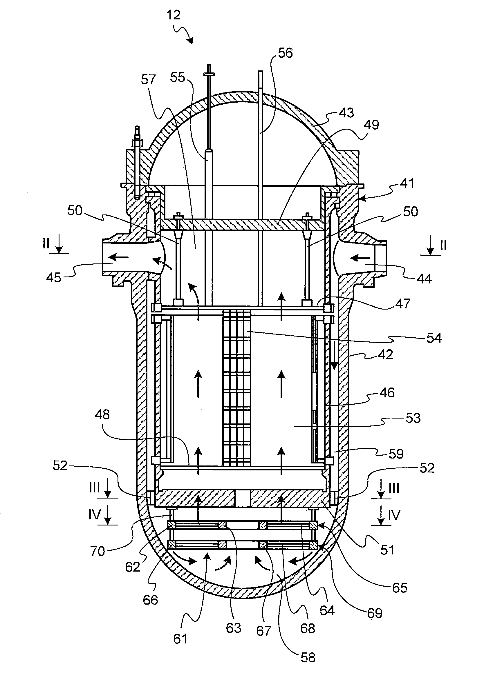
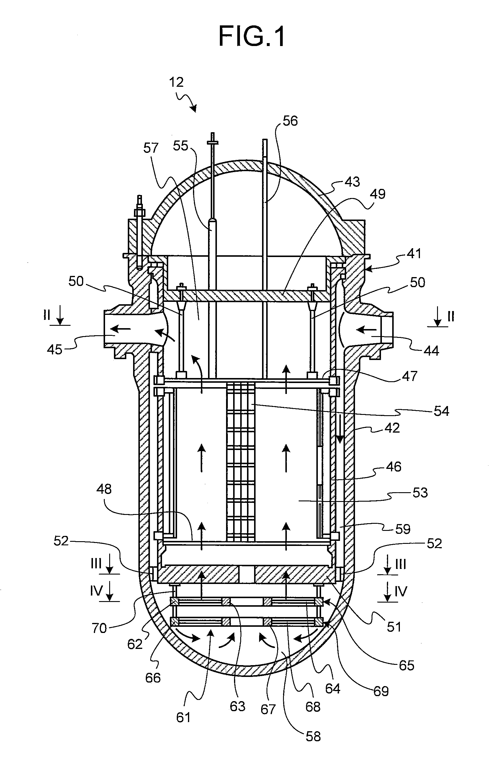
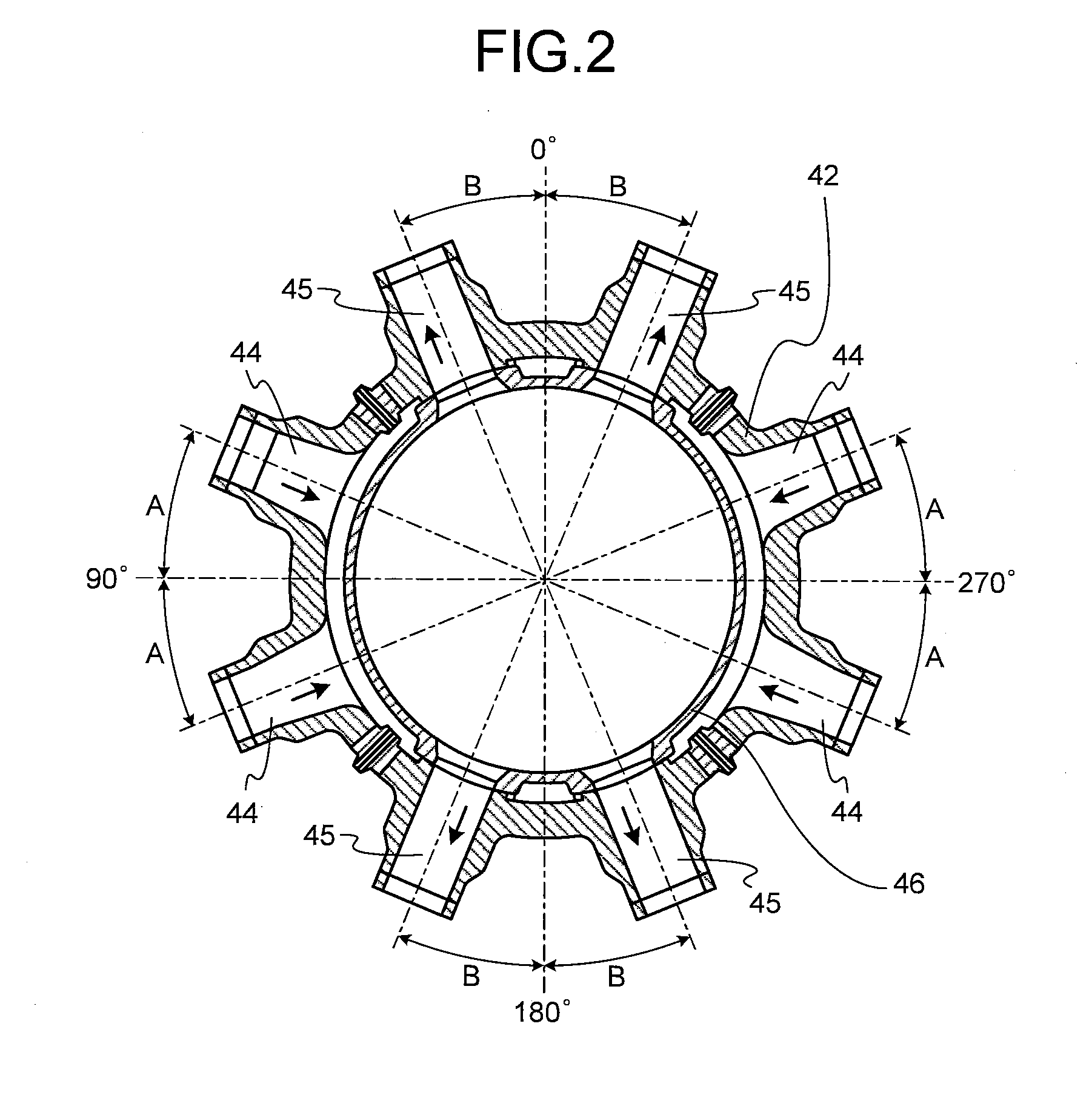
[0080]FIG. 1 is a schematic of an internal configuration of a pressurized water reactor according to a first embodiment of the present invention. FIG. 2 is a sectional view taken along the line II-II in FIG. 1. FIG. 3 is a sectional view taken along the line III-III in FIG. 1. FIG. 4 is a sectional view taken along the line IV-IV in FIG. 1. FIG. 5 is a schematic of a nuclear power plant that includes the pressurized water reactor according to the first embodiment.

[0081]A nuclear reactor according to the first embodiment is a pressurized water reactor (PWR) that uses light water as nuclear reactor coolant and neutron moderator, as high-temperature and high-pressure water that does not boil in the entire core. The nuclear reactor sends the high-temperature and high-pressure water to a steam generator by which steam is generated by heat exchange, and sends the steam to a turbine generator to produce electricity.

[0082]In a nuclear power plant that includes the pressurized water reactor ...

second embodiment

[0102]FIG. 6 is a horizontal sectional view of a straightener member provided in a pressurized water reactor according to a second embodiment of the present invention. Because the overall configuration of a nuclear reactor according to the present embodiment is similar to that in the first embodiment, it will be described with reference to FIG. 1. The same reference numerals are denoted to portions having the same functions as those of the embodiment, and detailed descriptions thereof will be omitted.

[0103]In the nuclear reactor according to the second embodiment, as shown in FIGS. 1 and 6, the lower plenum 58 includes a straightener member 71 that uniformly disperses and straightens the light water supplied to the lower plenum 58 from the downcomer portion 59, and flows upward to the core 53 in the circumferential direction and the radial direction of the core 53.

[0104]The straightener member 71 includes the upper ring 65 in which the upper outer ring 62 and the upper inner ring 63...

third embodiment

[0110]FIG. 7 is a horizontal sectional view of a straightener member provided in a pressurized water reactor according to a third embodiment of the present invention. Because the overall configuration of a nuclear reactor according to the present embodiment is similar to that in the first embodiment, it will be described with reference to FIG. 1. The same reference numerals are denoted to portions having the same functions as those of the embodiment, and detailed descriptions thereof will be omitted.

[0111]In the nuclear reactor according to the third embodiment, as shown in FIGS. 1 and 7, the lower plenum 58 includes a straightener member 81 that uniformly disperses and straightens the light water supplied to the lower plenum 58 from the downcomer portion 59 and flows upward to the core 53, in the circumferential direction and the radial direction of the core 53.

[0112]The straightener member 81 includes the upper ring 65 in which the upper outer ring 62 and the upper inner ring 63 a...


PUM


Abstract

In a nuclear reactor, a core barrel (46) is disposed in a reactor vessel (41) having an inlet nozzle (44) and an outlet nozzle (45), a core (53) is disposed in the core barrel (46), a lower plenum (58) is partitioned by the reactor vessel (41) and a bottom portion of the core barrel (46), and a downcomer portion (59) is partitioned by the reactor vessel (41) and a side wall of the core barrel (46). The lower plenum (58) includes a straightening member (61) formed of an upper ring (65) and a lower ring (69) in a ring shape, and a plurality of spokes (64 and 68) radially arranged inside the rings (65 and 69), respectively. Heat exchange efficiency is enhanced by uniformly supplying coolant introduced into a pressure vessel to the core from the lower plenum in a radial direction and a circumferential direction.

Description

TECHNICAL FIELD[0001]The present invention relates to a nuclear reactor including a core. More specifically, the present invention relates to a cooling structure of a core.BACKGROUND ART[0002]In pressurized water reactors (PWRs), light water is used as nuclear reactor coolant and neutron moderator, serves as high-temperature and high-pressure water that does not boil in the entire primary system. The high-temperature and high-pressure water is sent to a steam generator by which steam is generated by heat exchange, and the steam is then sent to a turbine generator to produce electricity.[0003]In such pressurized water reactors, the core is cooled by introducing coolant into the nuclear reactor from outside, and circulating the coolant. In other words, the coolant flows in through a plurality of coolant inlet nozzles formed on a reactor vessel, flows down a downcomer portion provided between the reactor vessel and a core barrel, and reaches a lower plenum. The coolant then flows upwar...

Claims


Application Information

Patent Timeline
IPC IPC(8): G21C15/243
CPCG21C13/036Y02E30/40G21C15/04Y02E30/30
Inventor UDA, NOBUKIWATANABE, SHIGEYUKI
Owner MITSUBISHI HEAVY IND LTD
Why Eureka
Try Eureka