
Stent graft

Active Publication Date: 2010-11-11
COOK MEDICAL TECH LLC
View PDF13 Cites 10 Cited by
  • Summary
  • Abstract
  • Description
  • Claims
  • Application Information

AI Technical Summary

Benefits of technology

[0012]An advantage of this configuration is that is satisfies several design constraints. For example, it provides a flexible interconnection between the end stent and the next stent to enable the stent graft to more closely follow the inner curve of the aortic arch, and thus a more precisely aligned location of the stent graft in the body vessel. Furthermore, the configuration permits the stent graft, and in particular its proximal end, to be folded into a compact arrangement when compressed. This can be attributed, at least in part, to the absence of graft material where it is not required.
[0013]Preferably, the stents are formed of wire and the distal peaks of the bare stent overlap the proximal peaks of the next stent, at least in a compressed configuration of the stent graft member, by a distance equal to at least twice the thickness of the wire. This further assists in enabling a compact compressed configuration. Viewed circumferentially, there is effectively double thickness of wire at each stent peak; by avoiding alignment of the distal peaks of the proximal stent and the proximal peaks of the next stent, resistance to compression is avoided.
[0016]Preferably, the proximal peaks of the proximal stent have a greater radius of curvature than the distal peaks of the proximal stent. The relatively large radius of the proximal peaks avoids their undesired entry into side vessels of the aorta. The relatively small radius of curvature of the distal peaks contributes to a smaller volume of wire which assists in packing when the end of the stent is compressed.
[0018]In one preferred method, in the compressed configuration, there is a longitudinal overlap between the distal peaks of the end stent and the proximal peaks of the next stent. Where the stents are made of wire, the longitudinal overlap of the peaks is equal to at least twice the thickness of the wire. Thus although there is still an overlap of the stents, the distal peaks of the end stent are sufficiently out of longitudinal alignment with the proximal peaks of the next stent that a concentration of wire material in one place is avoided.

Problems solved by technology

A problem with the deployment of stent grafts in the aortic arch is that a satisfactory engagement against the interior of the body vessel wall has to be maintained at the same time as matching the curved shape of the aortic arch.

Method used


Image

  • Stent graft
  • Stent graft
  • Stent graft

Examples


Embodiment Construction

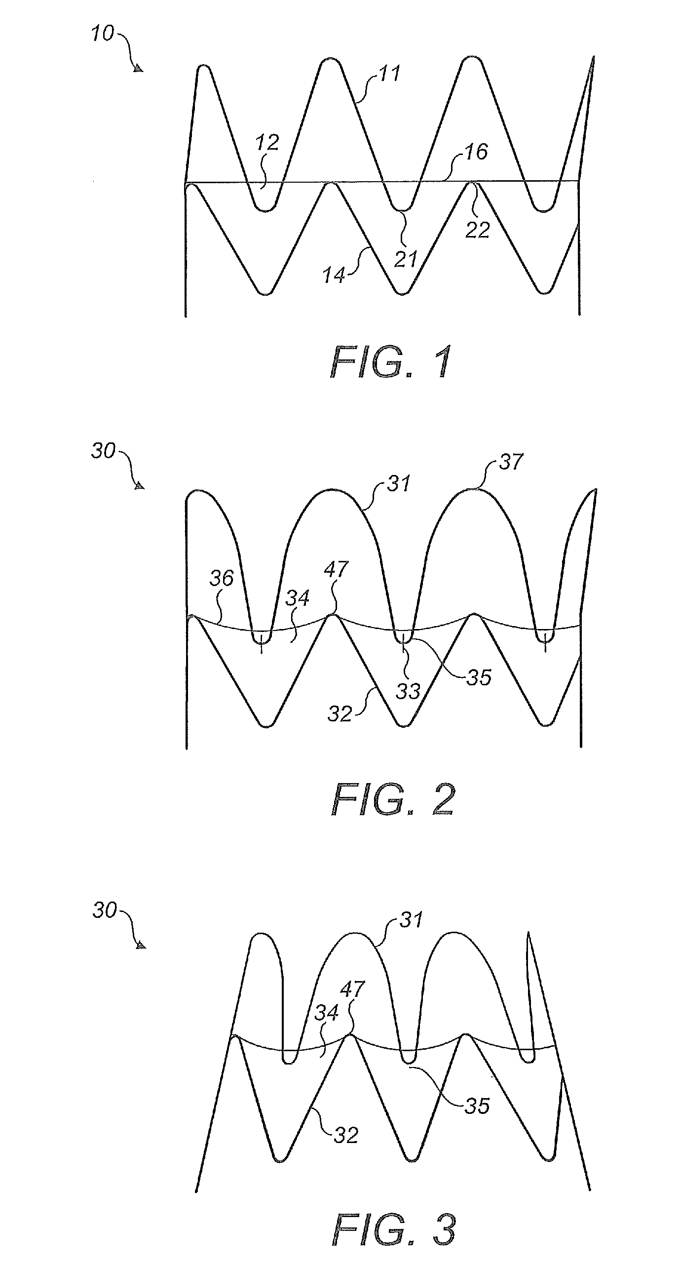
[0027]Referring to the drawings, FIG. 1 shows a stent graft 10 in accordance with the prior art. A proximal end stent 11 is substantially bare, that is only a relatively small part of the stent is covered with graft material 12. For most of its length, the wire forming stent 11 has no graft material on either side; at intervals, relatively short lengths of the wire have graft material on all sides. The next stent 14 is completely covered by the graft material. Viewed in the sideways or radial direction of the Figure, the end 16 of the graft material is a straight line. The graft material 12 and the stent members 11, 14 attached thereto are substantially circular in cross-section.

[0028]As seen in FIG. 1, the distal peaks 21 of stent 11 overlap the proximal peaks 22 of the next stent 12 in the longitudinal direction. The peaks 21 and 22 alternate in regular manner around the periphery of the stent graft.

[0029]Problems can arise when compressing the stent graft 10 for passage through a...


PUM

PropertyMeasurementUnit
Lengthaaaaaaaaaa
Lengthaaaaaaaaaa
Lengthaaaaaaaaaa

Abstract

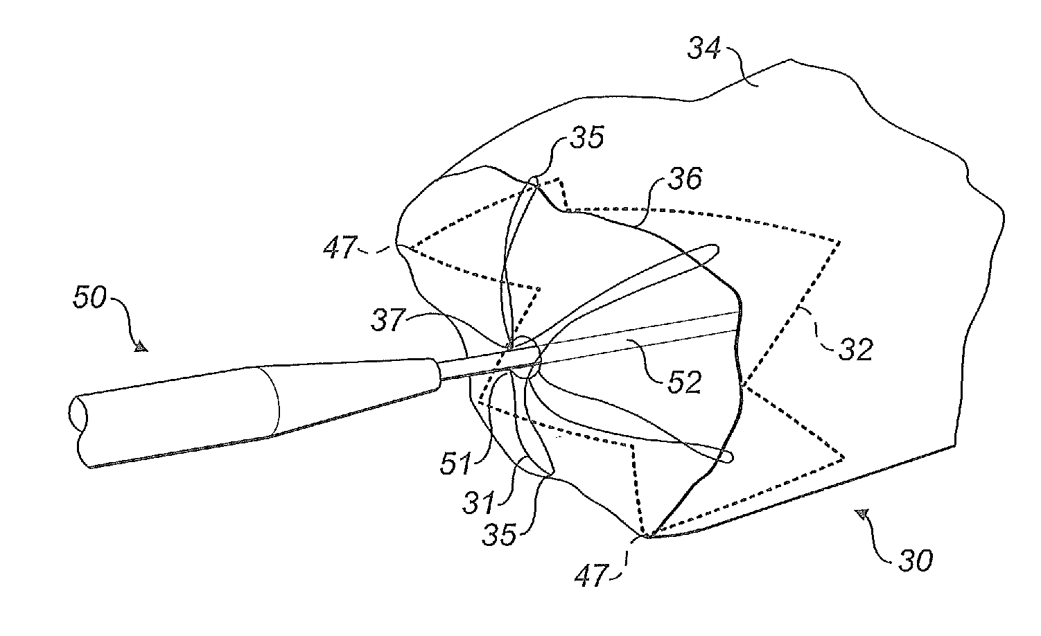
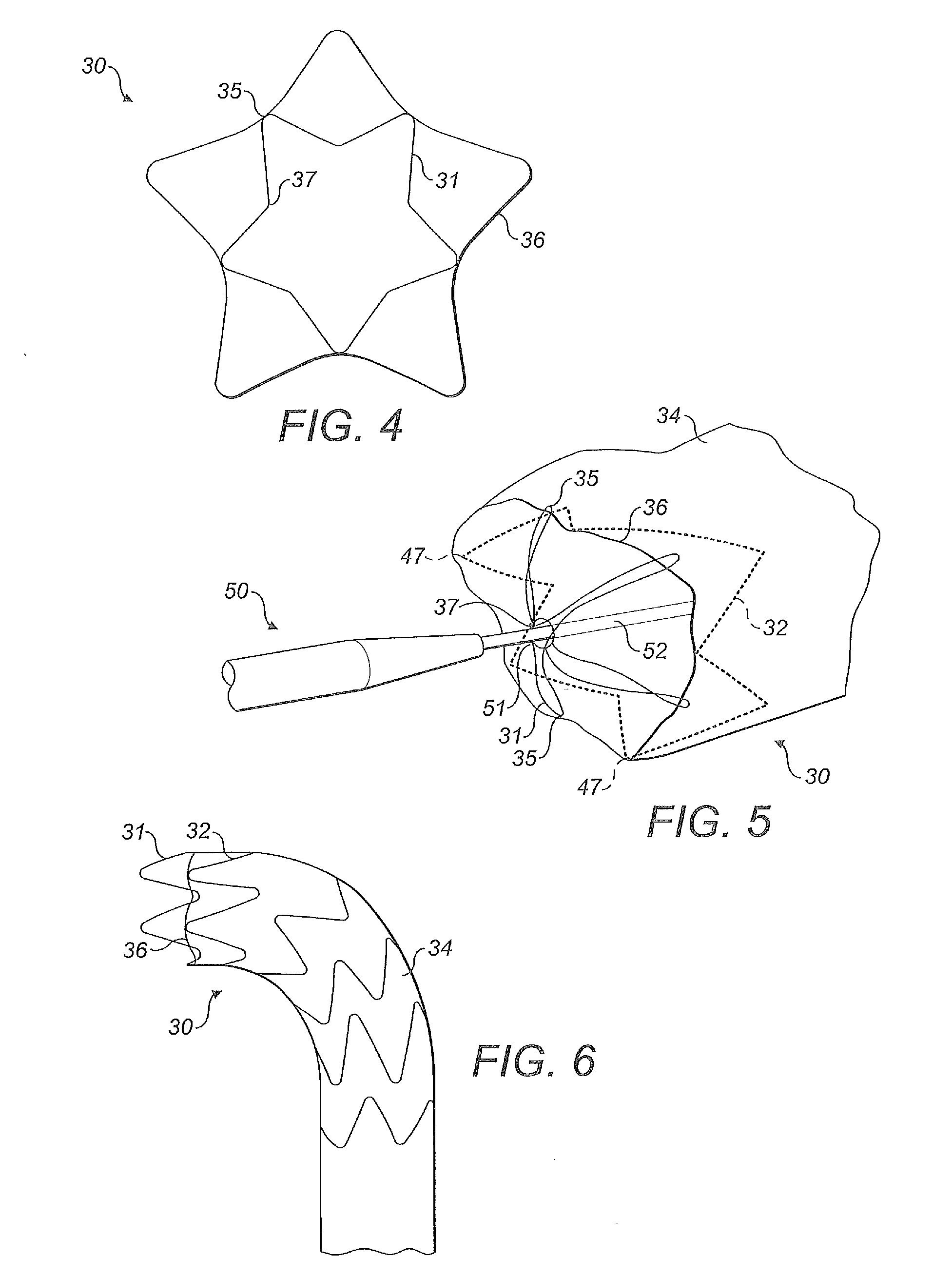
A stent graft 30 has a bare end stent 31 which partially overlaps the next stent 32 with the end 36 of the graft material 34 being shaped to follow the distal peaks 35 of the end stent and the proximal peaks 47 of the next stent. The proximal peaks 37 of the end stent have a greater radius of curvature than the distal peaks 35 of the end stent.

Description

TECHNICAL FIELD[0001]The present invention relates to a stent graft and in particular to a stent graft for deployment in a curved body vessel such as the aortic arch.BACKGROUND OF THE INVENTION[0002]A problem with the deployment of stent grafts in the aortic arch is that a satisfactory engagement against the interior of the body vessel wall has to be maintained at the same time as matching the curved shape of the aortic arch. Satisfying both constraints involves a compromise in design and conventional stent grafts do not bend satisfactorily around the aortic arch.[0003]Another design constraint is that the proximal end stent should be at least partly bare, i.e. have no graft material thereon, in order that blood flow may be maintained with side vessels.[0004]US 2005 / 0049674 A1 discloses a stent graft having a proximal end stent which is substantially bare. The distal end of the proximal stent partially overlaps with the proximal end of the second stent. Viewed from the side, the end...

Claims


Application Information

Patent Timeline
IPC IPC(8): A61F2/86B21D9/00A61F2/07A61F2/966
CPCA61F2/07A61F2/966A61F2002/075A61F2230/0054A61F2230/0013A61F2230/005A61F2/89
Inventor PETERSEN, JESPER SCHADESOERENSEN, MARIANNEMOERK, TINA
Owner COOK MEDICAL TECH LLC
Learn More