Air separation apparatus and method

a technology of air separation and air compressor, which is applied in the direction of lighting and heating equipment, laminated elements, solidification, etc., can solve the problems of not giving details regarding the design of the heat exchanger itself, the most efficient operation of the plant with respect to electrical power, and the use of more expensive coiled heat exchangers, etc., to achieve the effect of improving the overall power consumption of the air separation plant, improving the power consumption of the booster air compressor, and improving the unit power

Inactive Publication Date: 2010-11-18
PRAXAIR TECH INC
View PDF22 Cites 13 Cited by
  • Summary
  • Abstract
  • Description
  • Claims
  • Application Information

AI Technical Summary

Benefits of technology

[0017]It is further noted that with respect to the prior art discussed above and as graphically presented in Castle, a meaningful benefit is derived at an oxygen pressure of above about 55 bar (a). The reason for this is at lower oxygen pressures, the air pressure required to vaporize the oxygen, as given by the equation set forth above, is within 10 bar or less of an air pressure contemplated in such prior art. However, the inventors herein have calculated that such a 10 bar difference corresponds to a unit power improvement of operating within such equation of at most about 0.08 kW per 1000 cfh of oxygen produced which would translate into a decrease of about 1 percent of the power expended in a booster air compressor used in an air separation plant. This in turn would represent a decrease in the overall power expenditure in the air separation plant of less than one-half a percent. As one skilled in the art would recognize, from at least a financial standpoint, given the cost of electrical power, this is not a meaningful operational improvement. However, at oxygen pressures of above 55 bar (a) when operating at air pressures derived from the above equation much more meaningful unit power improvements can be obtained and the improvements are greater as the oxygen pressure increases. For example at 80 bar(a) oxygen, the improvement in power consumption of the booster air compressor would be about 4 percent and therefore an improvement in the overall power consumption of the air separation plant of about 2 percent. At the high end of the range, 150 bar(a) oxygen, the risks associated with operating a heat exchanger able to withstand the required air pressure outweigh any power benefit leading to the use of pressures lower than that given by the above equation albeit at a higher power consumption.
[0018]In any aspect of the present invention, the indirect heat exchange between the pumped liquid oxygen stream and the air can be conducted in a plate-fin heat exchanger. In this regard, in yet a further aspect of the present invention, a plate-fin heat exchanger is provided that comprises parting sheets separated by and connected to fins to form at least air passages for a compressed air stream and oxygen passages for a pumped liquid oxygen stream. In this regard, such air and oxygen passages are “at least” formed in that, as indicated above, the present invention is equally applicable to a heat exchanger dedicated to the heating of the pumped liquid oxygen. For example, in the air separation plant discussed above where a second heat exchanger is employed in the so called “banked” design, it can be dedicated to the heating the pumped liquid oxygen stream. The fins in at least the air passages have an undulating configuration. As can be appreciated, such a heat exchanger is configured to withstand an oxygen pressure of the pumped liquid oxygen stream in a range above about 55 bar(a) and no greater than about 150 bar(a) upon entering the heat exchanger and an air pressure of the compressed air stream, upon entering the heat exchanger, equal to a value within a range of no less than ten percent below and no greater than 20 percent above a quantity equal to 0.00003×(oxygen pressure)3−(0.01141×(oxygen pressure)2)+(2.263×(oxygen pressure)+2.5175.
[0019]In any aspect of the present invention, the fins in at least the air passages can be provided with a wavy or undulating configuration such that the flow path of the compressed air through the fins is increased over a straight through plain fin arrangement with the same fin thickness and pitch.
[0020]Preferably, the undulating configuration can have regular spaced points of maximum amplitude along a length dimension of each of the fins forming peaks and troughs of arcuate configuration. The peaks and the troughs are connected by straight segments of each of the fins. The wavelengths of the fins are preferably equal to about in a wavelength range no less than about 0.125 inches and no greater than about 1.5 inches.
[0021]When the oxygen pressure is at least about 80 bar(a), the air passages and the oxygen passages can have an identical configuration. The fins have a maximum amplitude greater than a pitch dimension as measured between adjacent fins. The fins can have a ratio of transverse thickness to the pitch dimension which is greater than about 0.4 multiplied by a factor that is equal to the air pressure divided by an allowable tensile stress equal to about the yield stress for a material forming the heat exchanger multiplied by a safety factor of not greater than about 0.5 and no less than about 0.15. The heat exchanger in any aspect of the present invention can be of brazed aluminum construction.

Problems solved by technology

In this regard, since the cryogenic rectification is conducted at cryogenic temperatures and there exists thermal loss due to heat leakage, liquid products that are removed from the plant for storage, backup or merchant liquid sale and warm end losses, refrigeration must be imparted.
It was mentioned, however, in the paper that such curve did not represent optimum conditions for the best power consumption of the plant and such optimum conditions were not presented in the paper.
However, at higher pressures, more expensive coiled heat exchangers would have to be used.
However, nothing is said in this patent regarding the most efficient operation of the plant with respect to the electrical power used in compressing the air.
Further, there are no details given regarding the design of the heat exchanger itself.
However, as will be discussed, such a design would lead to an inefficient heat exchanger with respect to the size required to accomplish the necessary heat exchange between air and pumped oxygen streams.

Method used


Image

  • Air separation apparatus and method
  • Air separation apparatus and method
  • Air separation apparatus and method

Examples


Embodiment Construction

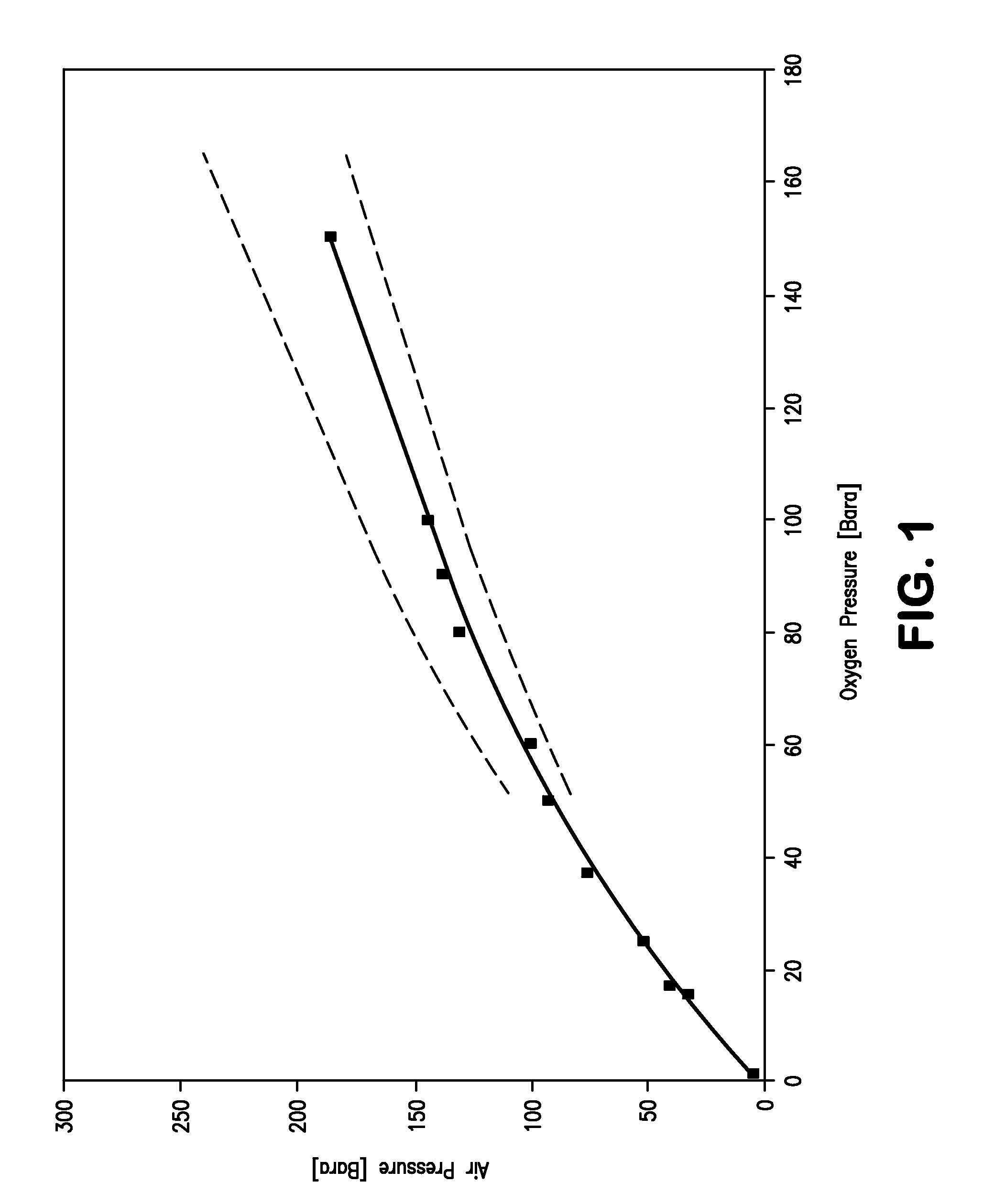
[0029]With reference to FIG. 1, the illustrated curve shown in a solid line represents the air pressure required to heat pumped liquid oxygen in accordance with the present invention at a particular oxygen pressure to produce an oxygen product as a result of the pumping and the heating as a supercritical fluid. When such air pressure is used, the minimum compression power will be obtained for a particular oxygen pressure.

[0030]As would be known in the art, the power expended in compressing the air has two components, namely, the pressure to which the air is to be compressed and the flow rate of the air. The air pressure and flow rate in turn must be sufficient to heat the oxygen at a specified flow rate and pressure from a pressurized liquid to a supercritical fluid after having passed through a heat exchanger. Obviously, the lower the flow rate of the air, the higher the required pressure and vice-versa that is required for a particular flow and pressure of the oxygen. Although the...


PUM


Abstract

The present invention relates to an air separation apparatus and method in which a pumped liquid oxygen stream is heated within a heat exchanger through indirect heat exchange with compressed air to produce an oxygen product. The liquid oxygen stream is pressurized in a range above about 55 bar(a) and no greater than about 150 bar(a) and is a supercritical fluid after having been heated within the heat exchanger. The air is compressed to an air pressure that is a function of the oxygen pressure that will result in a minimum power being expended in the compression of the air. The heat exchanger can be a brazed fin heat exchanger fabricated from aluminum in which the fins located in heat exchange passages have an undulating configuration to increase the flow path length and induce flow separation and thereby increase the heat transfer coefficient within the heat exchanger.

Description

RELATED APPLICATIONS[0001]This application is a continuation application of prior continuation application Ser. No. 12 / 648,775, filed Dec. 29, 2009, which is a continuation of, and claims priority from, application Ser. No. 12 / 363,279, filed Jan. 30, 2009. All of which are incorporated by reference herein in its entirety.FIELD OF THE INVENTION[0002]The present invention relates to an apparatus and air separation plant for forming an oxygen product as a supercritical fluid by heating a pumped liquid oxygen stream within a heat exchanger through indirect heat exchange with compressed air. More particularly, the present invention relates to such an apparatus and air separation plant in which the air pressure utilized in to heat the pumped liquid oxygen stream is selected on the basis of a function of the oxygen pressure that results in a minimum or very close to minimum expenditure of compression energy. Even more particularly, the present invention relates to such a apparatus and air ...

Claims


Application Information

Patent Timeline
Patent Type & Authority Applications(United States)
IPC IPC(8): F25J3/00
CPCF25J3/0409F25J3/04218F25J3/04296F25J3/04303F25J3/04309F25J3/04315F25J3/04066F25J5/002F25J2290/10F28D9/0062F28F3/025F25J3/04018F25J3/04412
Inventor JIBB, RICHARD JOHNSHELAT, MAULIK R.ZAMBRANO, LYDA
Owner PRAXAIR TECH INC
Why Eureka
Try Eureka