Device for determining the position of a piston in a cylinder

a technology of a cylinder and a position sensor, which is applied in the direction of engine testing, structural/machine measurement, instruments, etc., can solve the problems of more difficult to accurately determine the position of the piston, distortion, amplification or partial extinction the difficulty of measuring the transit time of the ultrasound signal along the main direction of the received signal, etc., to achieve redundancy of the measuring system, increase the measurement length, and improve the accuracy

Inactive Publication Date: 2010-11-18
TRUMA GERAETETECHNIK GMBH & CO
View PDF10 Cites 22 Cited by
  • Summary
  • Abstract
  • Description
  • Claims
  • Application Information

AI Technical Summary

Benefits of technology

[0051]The piston can be connected to a piston rod that is guided axially from the cylinder on a front-side end. The axial ultrasound facility can be arranged on the front-side end of the cylinder at which the piston rod is not guided out, whereas the transverse ultrasound facility is provided in an area of the front-side end of the cylinder, at which the piston rod is guided out. By this means, the position of the piston can be detected simultaneously from both sides and can therefore be determined at higher accuracy. The transverse ultrasound facility allows ultrasound to also be guided-in on the side of the piston that is already largely filled by the piston rod. Moreover, the measuring range, namely the measuring length, can be increased and / or a redundancy of the measuring systems can be attained for increased safety requirements.
[0052]The piston can be axially mobile in a main chamber of the cylinder and comprise on its front surface a step on which, in turn, the projection is formed. In corresponding fashion, a part-chamber that borders on the front side on the main chamber can be provided in the cylinder, with the internal layout of the part-chamber being designed such that the step can penetrate at least partially into the part-chamber and such that the part-chamber thereby becomes separated from the main chamber by the step. This means, though, that the step may initially be similar in shape to the projection and project from the remaining front surface of the piston. However, the step is not present such as to be isolated in all operating positions of the piston, but rather can penetrate into the part-chamber in a largely perfectly fitting fashion shortly before an end-position is reached and, in the course, essentially separates the part-chamber from the main chamber—except for a grease film. In this context, the step contacts the part-chamber and / or only a very small gap remains between the step and the wall of the part-chamber. This allows an end-position damping to be achieved for the piston when the fluid enclosed in the part-chamber can exit from the part-chamber only slowly.

Problems solved by technology

It has been evident that the ultrasound signal can occasionally be disturbed due to interference or scattering effects that render precise determination of the position of the piston 2 more difficult.
This leads to distortion, amplification or partial extinction of the signal received at the ultrasound transducer 6.
The difference between the received signals renders it more difficult to measure the transit time of the ultrasound signal along the main direction 14 precisely.

Method used


Image

  • Device for determining the position of a piston in a cylinder
  • Device for determining the position of a piston in a cylinder
  • Device for determining the position of a piston in a cylinder

Examples


Embodiment Construction

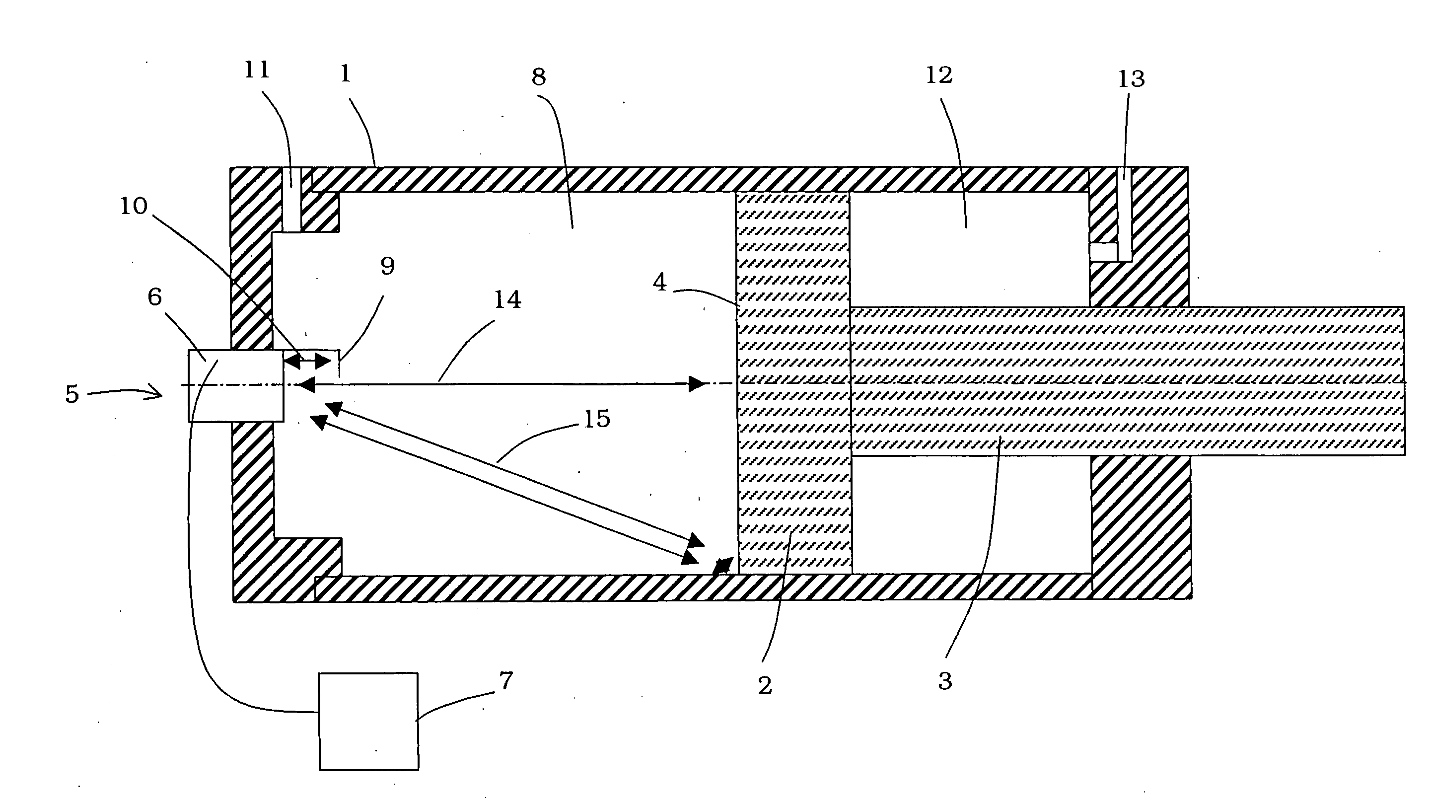
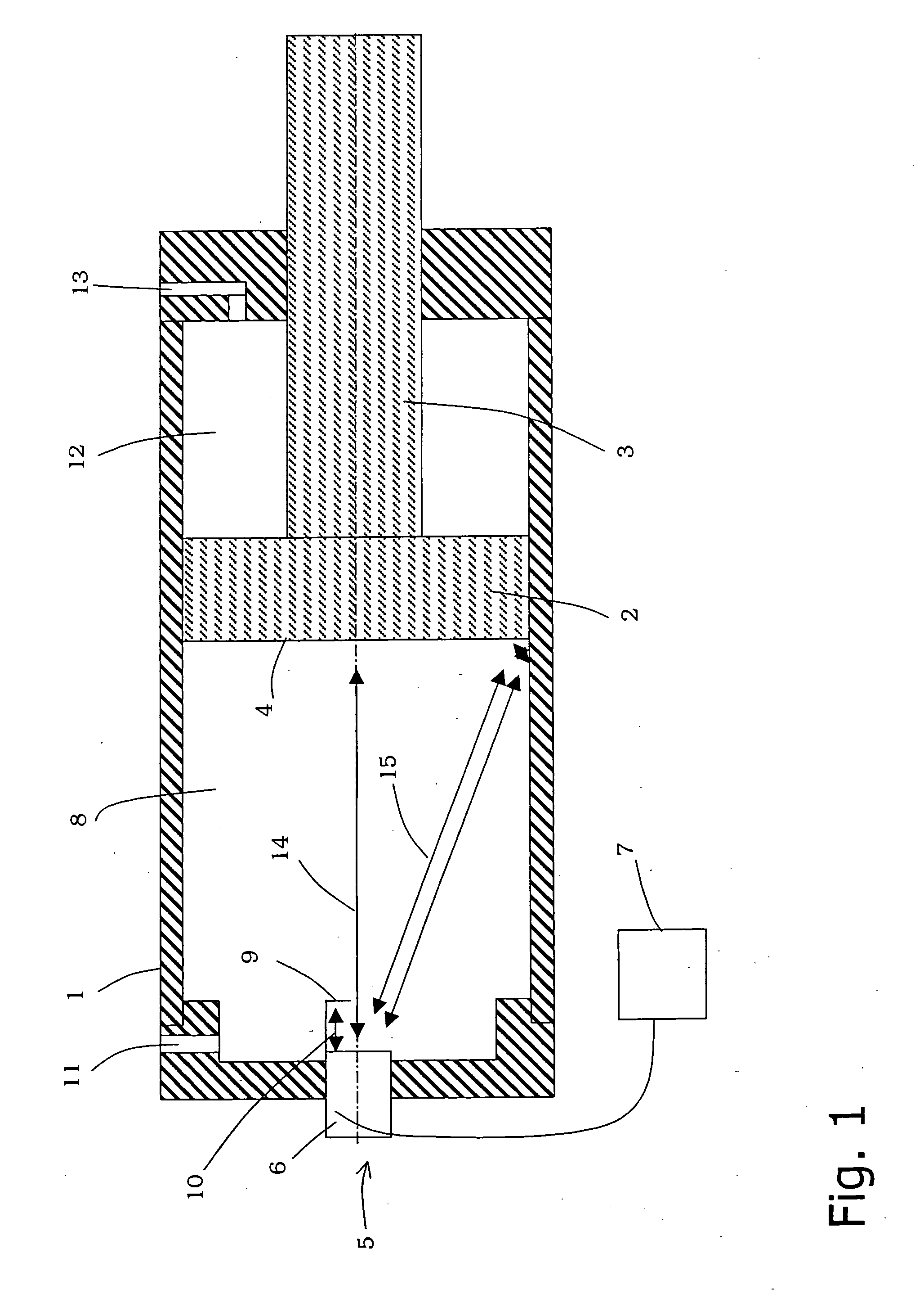
[0067]A known piston-cylinder unit having an ultrasound measuring device has already been described above based on FIG. 1. Therefore, in as far as identical or similar structural elements are used in the embodiments described in the following, the same reference numbers as in FIG. 1 are used.

[0068]In the embodiment of a piston-cylinder unit shown in FIG. 3, a projection 30 is provided on a front surface 4 of a piston 2 that faces an ultrasound transducer 6. The projection 30 comprises a front surface 31 that is raised by a distance and / or a height 32 from the remaining front surface 4 of the piston 2. A cylinder-shaped lateral surface 31a extends from the front surface 31 to the remaining front surface 4 of the piston 2. The projection 30 thus forms a wart on the piston 2.

[0069]The remaining front surface 4 of the piston 2 borders on an internal wall 33 of the cylinder 1 and is axially recessed with respect to the front surface 31 of the projection 30.

[0070]The front surface 31 of t...


PUM


Abstract

A device for determining the position of a piston in a cylinder comprises an ultrasound facility for transmitting ultrasound signals into the inside of the cylinder and for receiving ultrasound signals that are reflected from said piston. A projection is provided on a front surface of the piston and comprises a front surface that is offset by a certain height with respect to the remaining front surface of the piston. The projection is isolated in any piston position that can be reached during operation. The position of the piston is determined by an analytical facility based on the transit time of the ultrasound signals between the ultrasound facility and the front surface of the projection.

Description

[0001]This application is a National Stage application of International Application No. PCT / EP2008 / 005283, filed on Jun. 27, 2008 and claims priority of German Application Serial No. DE 10 2007 035 252.4 filed Jul. 27, 2007.BACKGROUND OF THE INVENTION[0002]1. Field of the Invention[0003]The invention relates to a device for determining the position of a piston in a cylinder through the use of ultrasound signals.[0004]2. Description of the Prior Art[0005]An ultrasound position measuring system is known from DE 103 22 178 A1, in which an ultrasound transducer transmits ultrasound signals into a cylinder in the direction of a front surface of a piston and receives the ultrasound signals that are reflected from there. The distance of the front surface of the piston from the ultrasound transducer and thus the position of the piston within the cylinder can be determined based on the transit time of the ultrasound signals, provided the velocity of sound in the medium is known.[0006]A simil...

Claims


Application Information

Patent Timeline
Patent Type & Authority Applications(United States)
IPC IPC(8): G01M15/06
CPCG01B17/00G01S15/02F15B15/2884G01S15/88G01S15/08G01S7/52006G01S2007/52014
Inventor VOLKWEIN, THOMAS
Owner TRUMA GERAETETECHNIK GMBH & CO
Why Eureka
Try Eureka