Subsea connector

a technology of connectors and connectors, applied in the direction of couplings, sealing/packing, borehole/well accessories, etc., can solve the problems of assembly not being appropriately secured to the wellhead, misalignment, and possible misalignment between the locking means of the connector and the locking profile of the wellhead

Active Publication Date: 2010-11-18
AKER SOLUTIONS AS
View PDF15 Cites 52 Cited by
  • Summary
  • Abstract
  • Description
  • Claims
  • Application Information

AI Technical Summary

Benefits of technology

[0016]One embodiment of a subsea connector assembly includes a connector having a central bore with an upper locking profile. The upper locking profile is adapted to engage a corresponding profile on a spool body. The spool body may be inserted into the central bore of the connector and rotated so that the profiles engage each other locking the spool body to the connector to form a connector assembly that may be landed onto a wellhead member. The connector includes a locking means that is adapted to engage a locking profile of the wellhead member to selectively secure the connector assembly to the wellhead member. The locking profiles of the connector and spool body may provide that the spool body is inserted into the connector at a desired angular orientation. The connector assembly may include a key that may be inserted into a keyway to prevent further rotation of the spool body with respect to the connector after the spool body has been secured to the connector to make up the connector assembly. The spool body may include an inner locking profile in a central bore of the spool body to engage additional equipment or another portion of a spool body. The locking profiles of the connector and the spool body may be a breech lock profile.

Problems solved by technology

Variances in the dimension tolerances of each component of the connector assembly can buildup in the aggregate causing the potential misalignment between the locking means of the connector and the locking profile of the wellhead.
Another potential problem exists in providing the proper angular alignment between the subsea connector and the wellhead.
Further, the misalignment of components may cause the assembly to not be appropriately secured to the wellhead.
Misalignment may also arise due to the manner in which the connector is bolted to the wellhead.
The misalignment of the connector with respect to the wellhead may cause a decrease in the preload force on the subsea connector.
The connection or adjustment of prior subsea connectors to achieve a desired preload force can take a significant amount of time, for example in excess of 10 hours.
Dimension tolerance buildup of the components and / or variations in the wellhead may cause the misalignment of the lock ring 365 with the locking profile resulting in a connection to the wellhead that may be tighter or looser than expected.
As would be appreciated by one of ordinary skill in the art, the preload force on the system when secured to the wellhead member may be affected due to tolerance variances for each part or due to variances in the profile of the wellhead member.

Method used


Image

  • Subsea connector
  • Subsea connector
  • Subsea connector

Examples


Embodiment Construction

[0059]Illustrative embodiments are described below as they might be employed in a subsea connector. In the interest of clarity, not all features of an actual implementation are described in this specification. It will of course be appreciated that in the development of any such actual embodiment, numerous implementation-specific decisions must be made to achieve the developers' specific goals, such as compliance with system-related and business-related constraints, which will vary from one implementation to another. Moreover, it will be appreciated that such a development effort might be complex and time-consuming, but would nevertheless be a routine undertaking for those of ordinary skill in the art having the benefit of this disclosure.

[0060]Further aspects and advantages of the various embodiments will become apparent from consideration of the following description and drawings.

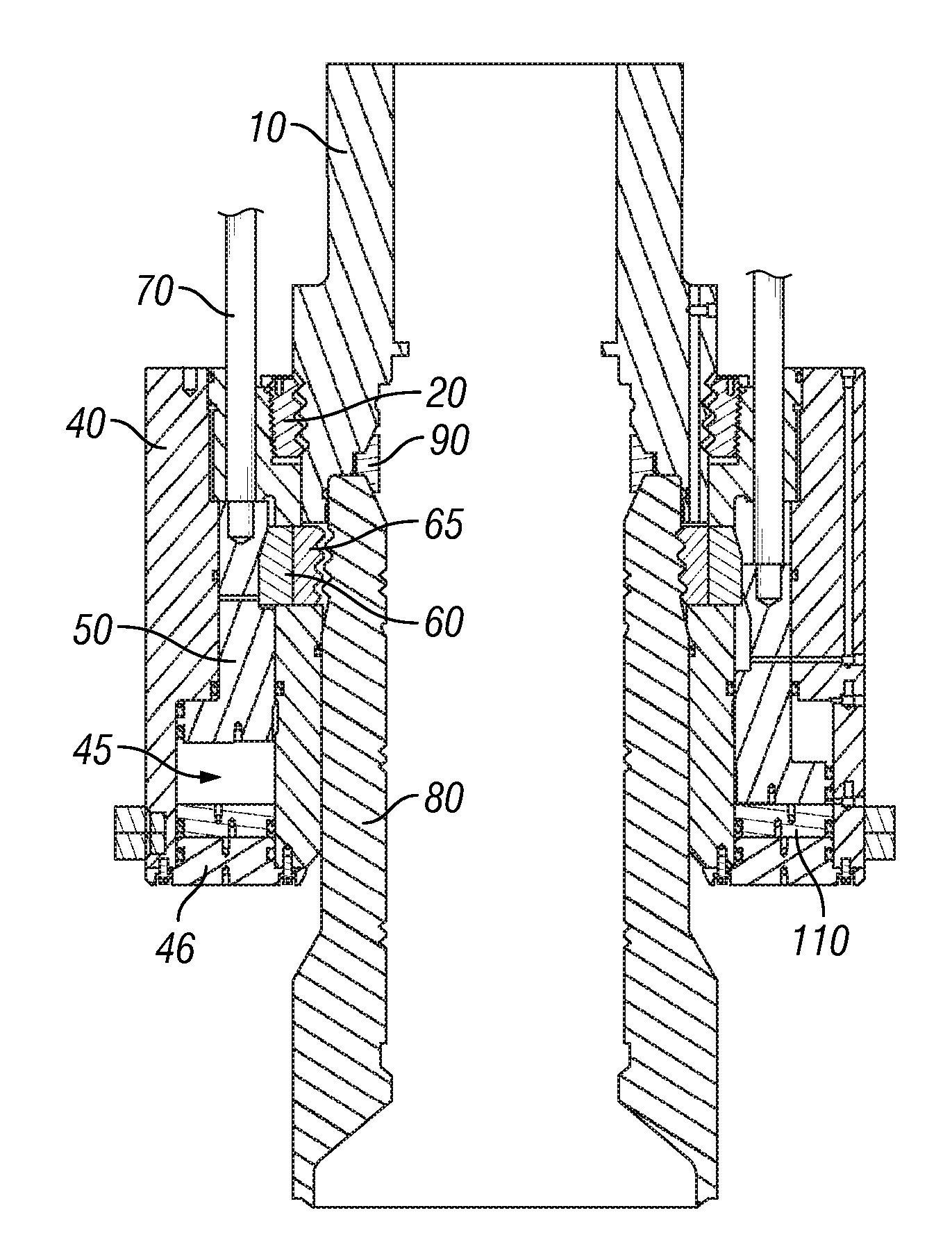
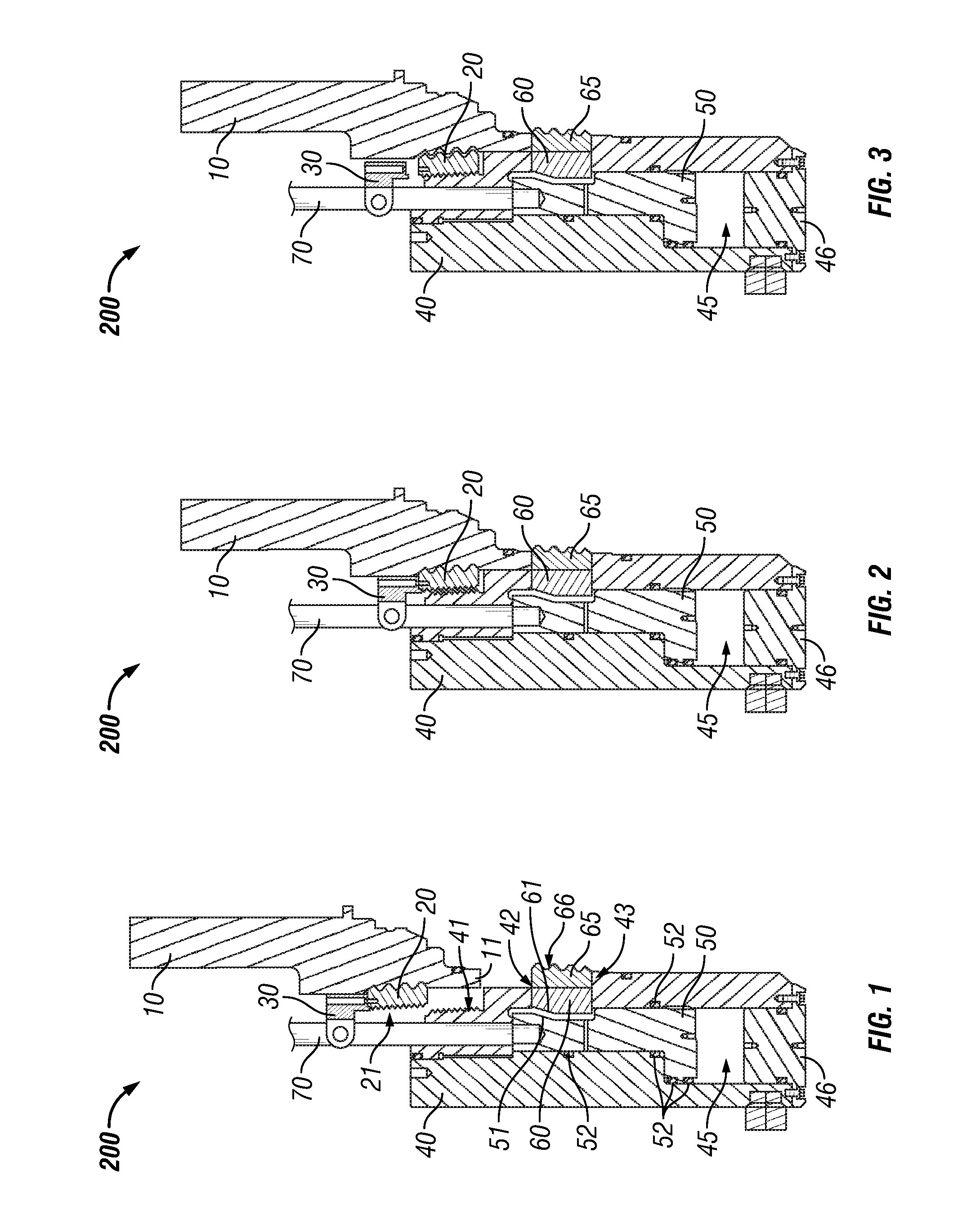
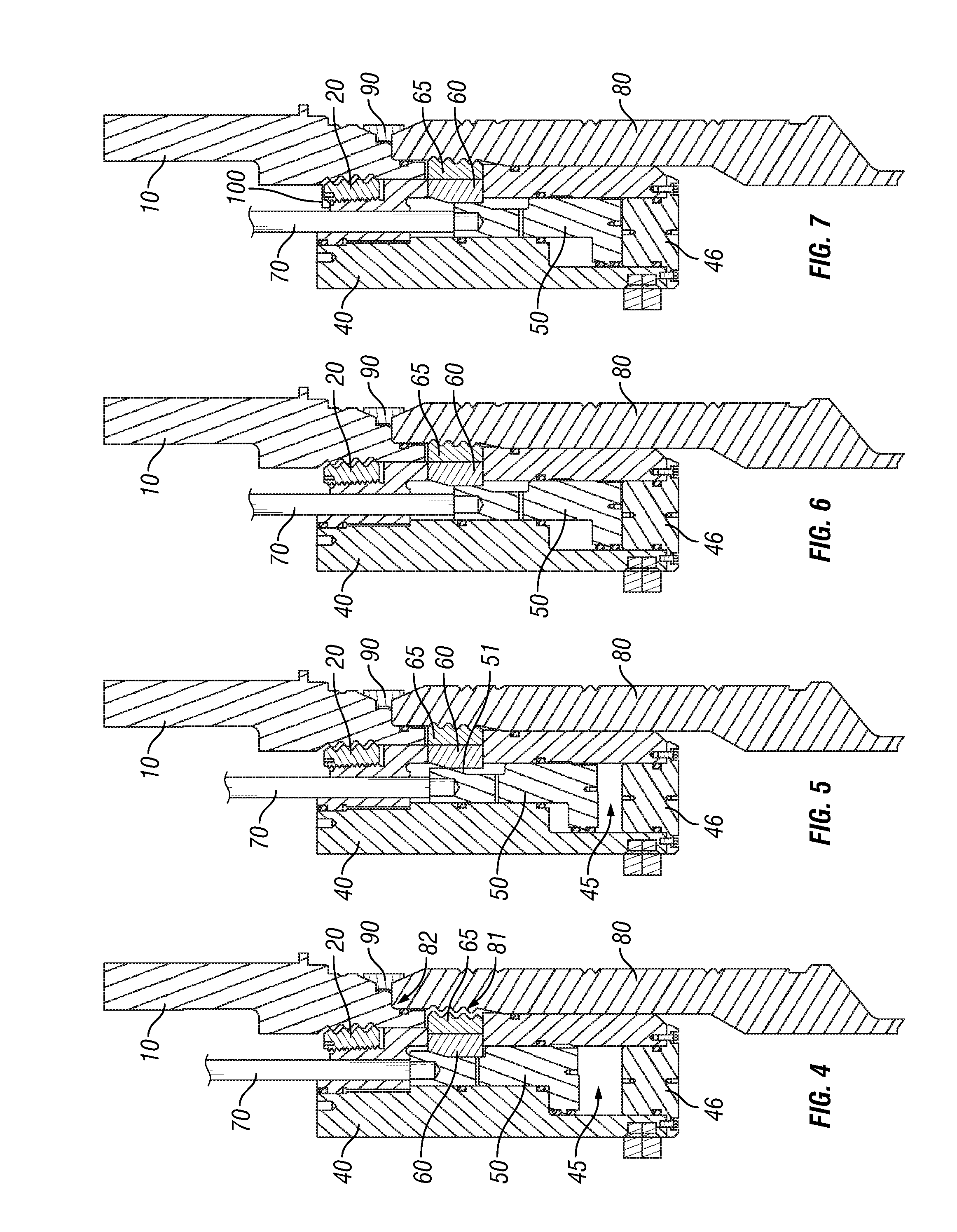
[0061]FIG. 1 shows a partial cross-section view of one embodiment of a subsea connector 200 with a spoo...


PUM


Abstract

A subsea connector that includes a connector capable of selectively connecting to a spool body to form a connector assembly. The subsea connector may include an adapter ring that is capable of connecting the spool body to the connector. The connector assembly may be lowered onto a wellhead member and locked into place by a movable piston and split lock ring. While the connector assembly is in the unlocked state, the adapter ring may be rotated moving the connector up or down with respect to the spool body, which lands on the wellhead member. The movement of the connector may be used to vary the alignment of the connector locking means with respect to the locking profile of the wellhead member. This change in position may be used to modify the preload force applied to the connector when locked onto the wellhead member.

Description

RELATED APPLICATIONS[0001]The present application claims benefit of priority to U.S. Provisional Application No. 61 / 155,226 entitled “Subsea Connector,” which was filed Feb. 25, 2009, the disclosure of which is hereby incorporated by reference in its entirety.BACKGROUND[0002]1. Field of the Disclosure[0003]The present disclosure generally relates a subsea connector that includes an adjustment ring that may be used to change the positional relationship between a spool body and a connector of a connector assembly. The change in the positional relationship may be used to vary the preload force applied to the subsea connector when secured to a wellhead member. One embodiment is a subsea connector assembly comprising a spool body rotatably connected to a connector having corresponding locking profiles. The locking profile may be a breech lock profile.[0004]2. Description of the Related Art[0005]Connectors of various types are used to connect equipment to subsea wellheads. A common type o...

Claims


Application Information

Patent Timeline
Patent Type & Authority Applications(United States)
IPC IPC(8): F16L25/00F16L1/26
CPCE21B33/038
Inventor CUIPER, GLEN H.PAULO, PAULO C.S.
Owner AKER SOLUTIONS AS
Why Eureka
Try Eureka