Supercharge Your Innovation With Domain-Expert AI Agents!

Power converter for vehicle

a power converter and vehicle technology, applied in the field of vehicle power converters, can solve the problems of narrow operation area in which synchronous rectification can be performed, affecting the efficiency of synchronous rectification, and generating elements, and achieves high-efficiency synchronous

Active Publication Date: 2010-11-18
MITSUBISHI ELECTRIC CORP
View PDF2 Cites 4 Cited by
  • Summary
  • Abstract
  • Description
  • Claims
  • Application Information

AI Technical Summary

Benefits of technology

The present invention provides a vehicle power converter that can efficiently convert between DC power and AC power. It includes a controller that can detect the load state of the power generator-motor and shift from diode rectification to synchronous rectification or from synchronous rectification to diode rectification accordingly. This prevents failure of synchronous rectification during load shifts and ensures highly efficient operation even at low load states. The shift condition is also made variable based on the power generation voltage, which expands the range of operation for synchronous rectification. Overall, this invention provides a highly efficient vehicle power converter.

Problems solved by technology

However, synchronous rectification based on switching elements has been recently used in place of diode rectification because it has higher efficiency and heat generation of elements is less.
That is, when the rectification style is shifted from the diode rectification to the synchronous rectification under a low-rotation and low-load state, the induced voltage is lowered due to execution of the synchronous rectification, and thus on-timing and off-timing of diodes for comparing the induced voltage and a voltage Vp at a positive side terminal P for generation cannot be accurately calculated, and thus the synchronous rectification may fail.
Therefore, there is a problem that an operation area in which the synchronous rectification can be performed is narrow when the power generation voltage is high.

Method used


Image

  • Power converter for vehicle
  • Power converter for vehicle
  • Power converter for vehicle

Examples


first embodiment

[0032]A vehicle power converter according to a first embodiment of the present invention will be described in detail.

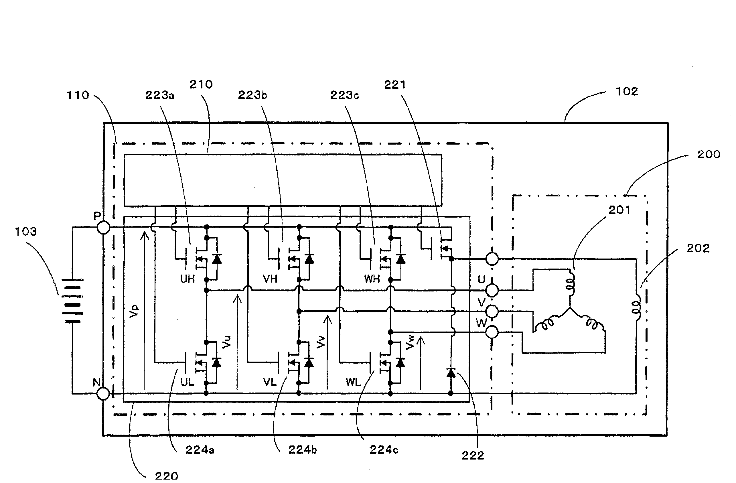
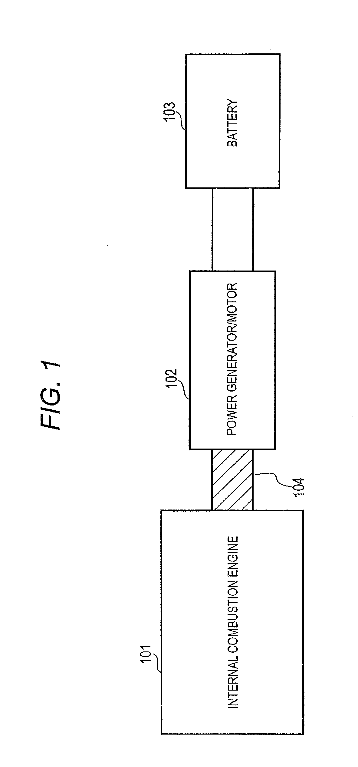
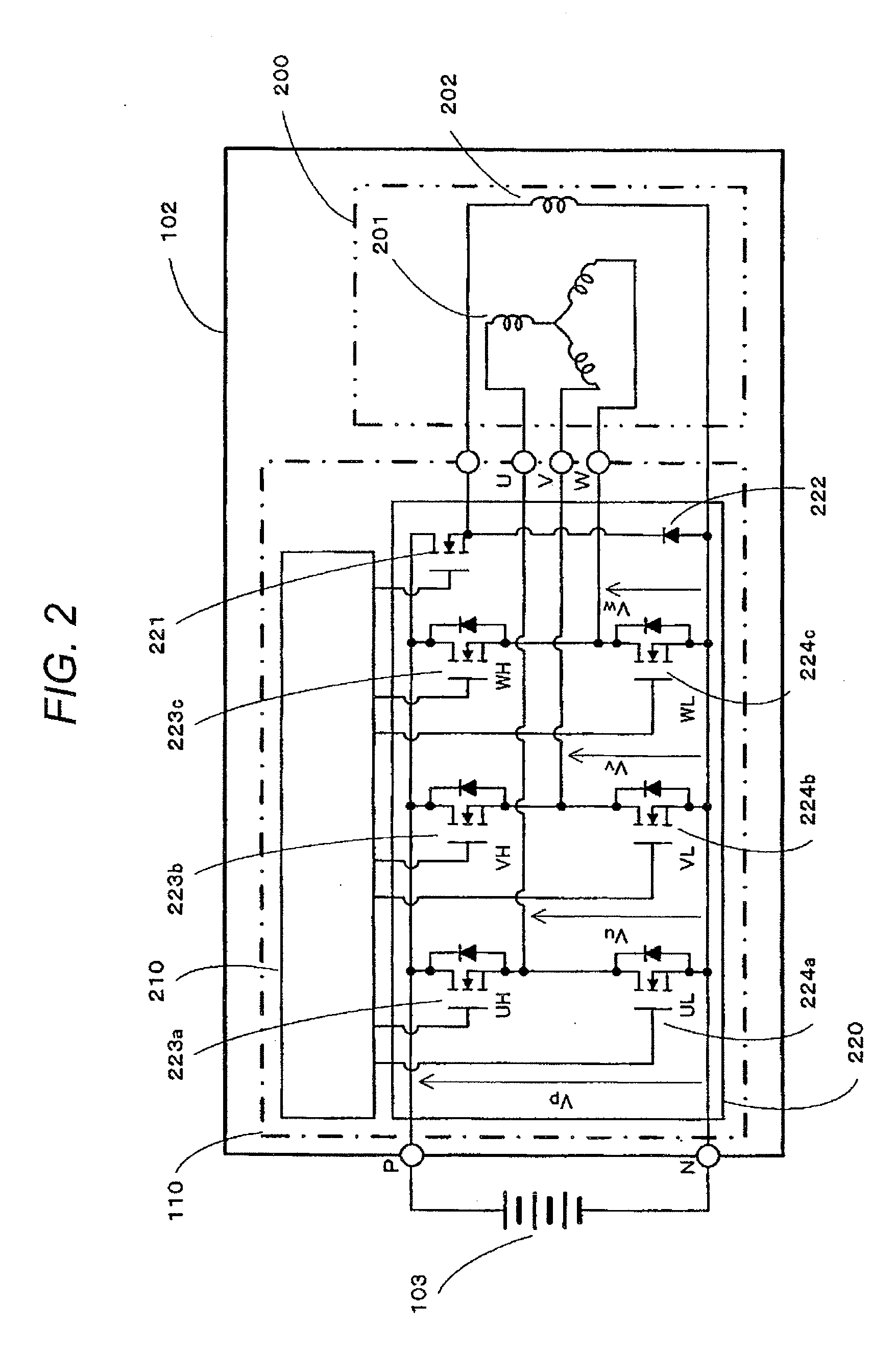
[0033]FIG. 1 is a diagram showing a vehicle system using a power generator-motor as a rotating electric machine, FIG. 2 is a diagram showing the construction of the power generator-motor provided with the vehicle power converter according to the first embodiment of the present invention, and FIG. 3 is a block diagram showing the construction of a controller for the power converter according to the first embodiment of the present invention.

[0034]In FIG. 1, an internal combustion engine 101 is connected to a power generator-motor 102 through a power transmission unit 104 such as a belt or the like, for example, and electrical energy is charged into a battery 103 through AC-DC conversion of the power generator-motor 102 during operation of the internal combustion engine 101.

[0035]In FIG. 2, the power generator-motor 102 comprises a power converting device 110 and a motor...

second embodiment

[0049]A second embodiment according to the present invention will be described with reference to the drawings.

[0050]FIG. 9 shows the construction of the load state detecting unit 305 for implementing the controller for the power generator-motor according to the second embodiment. The difference of this embodiment from the first embodiment resides in that a power generation voltage Vb of the power generator-motor 102 is input to the load state detecting unit 305.

[0051]In the first embodiment, the synchronous rectification permitting threshold value and the synchronous rectification prohibiting threshold value are dependent on the rotational speed, but the power generation voltage is not set as a parameter. Actually, when the power generation voltage is low, the power generation current for the shift from the diode rectification to the synchronous rectification can be reduced. However, when the power generation voltage increases, the power generation current for the shift from the dio...

third embodiment

[0056]A third embodiment according to the present invention will be described with reference to the drawings.

[0057]FIG. 13 shows the construction of the load state detecting unit for implementing the controller of the power generator-motor according to the third embodiment. The difference of this embodiment from the first and second embodiments resides in that an ON timing angle θon of the diode and a power generation voltage Vb are input to the load state detecting unit 305. The ON timing angle is obtained by detecting a rotational position (angle) from a rotational position sensor (resolver or encoder) indicating the rotational position of the power generator-motor or the like. Here, the ON timing angle of the diode means an energization (current passing) angle (not more than 180 deg) at which the diode is set to ON.

[0058]In the first embodiment, the rotational speed and the field current are input to the load state detecting unit 305, and in the second embodiment the power genera...


PUM


Abstract

A vehicle power converter including a plurality of switching elements having diodes connected thereto in parallel and constituting a multi-phase bridge circuit and a controller for conducting the switching element corresponding to each diode in synchronization with a conduction state of the diode concerned to perform synchronous rectification and is connected between a power generator-motor driven from the external to generate multi-phase AC power and DC equipment, further includes a load state detecting unit for detecting a load state of the power generator-motor when the multi-phase AC power occurs, wherein a shift from diode rectification to synchronous rectification or a shift from the synchronous rectification to the diode rectification is carried out in accordance with an output of the load state detecting unit.

Description

BACKGROUND OF THE INVENTION[0001]1. Field of the Invention[0002]The present invention relates to a vehicle power converter that is connected between an AC generator-motor and a DC power supply.[0003]2. Description of the Related Art[0004]A vehicle power converter for performing power conversion between DC power and AC power is used for a vehicle generator-motor which is mounted in a vehicle and driven to start up an engine and generates electric power after the engine is driven.[0005]In general, such a vehicle power converter is connected between a power generator-motor and a battery, and it comprises a plurality of switching elements and diodes elements connected to the respective switching elements in parallel (for example, parasitic diodes appended to the switching elements). When the power generator-motor operates as an electric motor, DC power from the battery is converted to AC power by controlling ON / OFF of the switching elements. On the other hand, when the power generator-m...

Claims


Application Information

Patent Timeline
Patent Type & Authority Applications(United States)
IPC IPC(8): B60L1/00
CPCH02J7/1492Y02T10/92H02M2007/2195H02M7/797H02M7/2195
Inventor NAKAJIMA, KENJIAKITA, KENICHIMORI, MASATOTABATA, MISTSUNORITSUJIMOTO, KATSUYA
Owner MITSUBISHI ELECTRIC CORP
Features
  • R&D
  • Intellectual Property
  • Life Sciences
  • Materials
  • Tech Scout
  • Unparalleled Data Quality
  • Higher Quality Content
  • 60% Fewer Hallucinations
Learn More