LED bulb and lighting apparatus

a technology of led bulbs and lighting devices, which is applied in the direction of lighting and heating devices, fixed installations, semiconductor devices for light sources, etc., can solve the problems of increasing manufacturing costs and shorten the life of lighting circuits, increase manufacturing costs, and increase heat toleran

Inactive Publication Date: 2010-11-18
TOSHIBA LIGHTING & TECH CORP +1
View PDF80 Cites 56 Cited by
  • Summary
  • Abstract
  • Description
  • Claims
  • Application Information

AI Technical Summary

Benefits of technology

[0006]According to Patent Document 1, however, since the lighting circuit is accommodated inside the apparatus body, when heat generated by the LED is dissipated through the heat dissipating fin to an external atmosphere, the heat is also transmitted to the lighting circuit included in the heat dissipating unit. Accordingly, the temperature of components of the lighting circuit rises during the lighting (glowing) time of the LED, and hence, the life of the lighting circuit is significantly shortened. On the other hand, in order to maintain the usable life of the lighting circuit, it becomes necessary to use components having a higher heat tolerance, which results in increasing in manufacturing cost.
[0007]An object of the present invention is to provide an LED bulb and a lighting apparatus in which the temperature of a lighting circuit is suppressed from rising during the lighting of an LED so as to preferably maintain life of the lighting circuit without increasing cost of components.

Problems solved by technology

On the other hand, in order to maintain the usable life of the lighting circuit, it becomes necessary to use components having a higher heat tolerance, which results in increasing in manufacturing cost.

Method used


Image

  • LED bulb and lighting apparatus
  • LED bulb and lighting apparatus
  • LED bulb and lighting apparatus

Examples


first embodiment

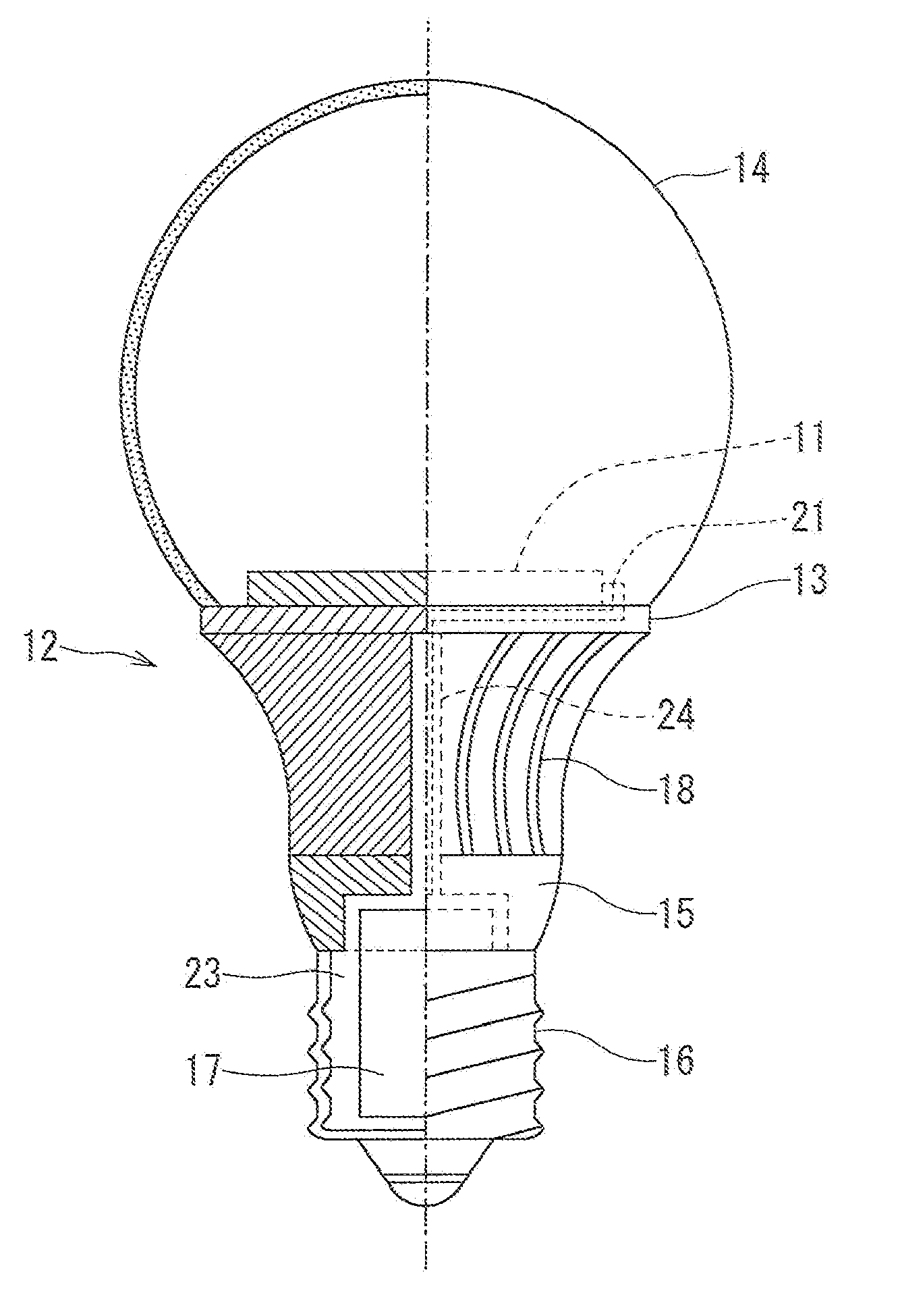
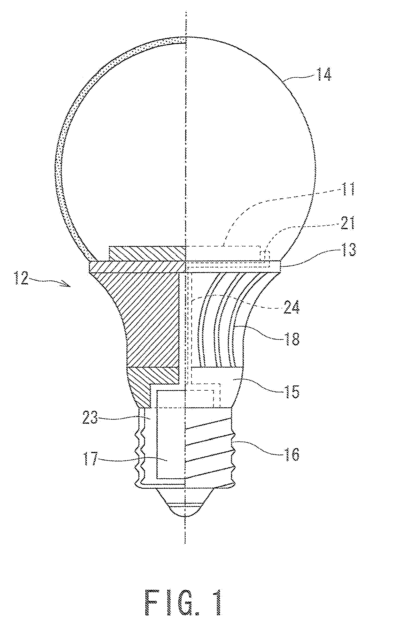
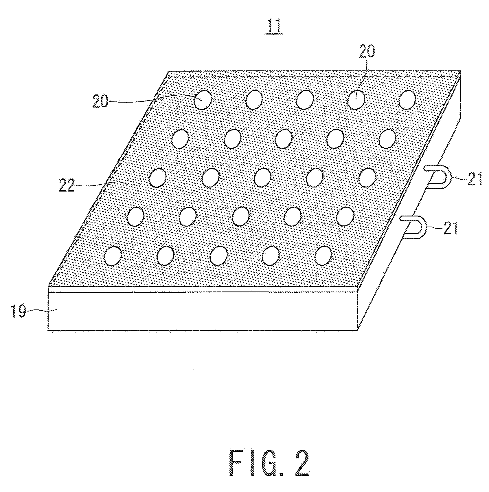
[0045]FIG. 1 is a front view of an LED bulb according to the present invention, in which a left half side is shown in section. An LED module 11 having a plurality of LEDs (surface-mounted thereon) is mounted on a heat dissipating (radiating) plate 13 of a heat dissipating (radiating) unit 12 in a manner contacting the heat dissipating plate 13. A glove 14 is mounted in the heat dissipating plate 13 of the heat dissipating unit 12 so as to cover the LED module 11, and a and radiant light from the LEDs of the LED module 11 is externally radiated through the glove.

[0046]A cap 16 is mounted via an insulating member 15 made of synthetic resin on a side opposite to the glove 14 of the heat dissipating unit 12. The cap 16 has an inner hollow portion, and a lighting circuit 17 for lighting (glowing) the LEDs is incorporated in an inner hollow portion 23 of the cap 16.

[0047]In the heat dissipating unit 12, the LED module 11 is, as described above, mounted on the heat dissipating plate 13, an...

second embodiment

[0070] the insulating unit 15 and the support portion 25 adjoining the heat dissipating fin 18 have a substantially cone-shaped configuration gradually projecting in a direction of the central portion. Accordingly, air circulating through the heat dissipating fin 18 readily enters the inside of the heat dissipating unit 12, and the air smoothly flows, thus improving the heat dissipation effects.

[0071]Further, a groove for arranging the line 21 of the LED module 11 is formed in the support portion 25 of the heat dissipating unit 12. Accordingly, the thickness of the support portion 25 is greater than that of the heat dissipating plate 13 of the first embodiment. Thus, the groove for arranging the line 21 of the LED module 11 can be easily formed. Furthermore, the end, on the side of the cap 16, of the heat dissipating fin 18 is engaged with the groove 26 of the insulating unit 15, so that the torsion strength is ensured between the heat dissipating unit 12 and the insulating unit 15,...

third embodiment

[0080] the. LED module 11, the heat dissipating unit 12, the insulating unit 15 and the cap 16 are arranged in this order, and since the thermal separation is performed by the insulating unit 15, the heat dissipation for the LED module 11 is mostly performed by the heat dissipating unit 12 and the heat dissipation for the lighting circuit 17 is performed by the cap 16, thus improving the heat dissipation characteristics in the entire structure.

[0081]Furthermore since the base end portions 18a of the heat dissipating fins 18 on the central axis side of the heat dissipating unit 12 are formed so as to be closer to the central axis side than the portion having the maximum diameter D of the insulating unit 15, thus improving the heat dissipation efficiency.

[0082]FIG. 8 is an explanatory view of a fourth embodiment of the present invention, in which FIG. 8(a) is a front view of an LED bulb according to the fourth embodiment of the present invention, and FIG. 8(b) is a front view of the L...


PUM


Abstract

An object of the present invention is to provide an LED bulb in which temperature of a lighting circuit is suppressed from rising during lighting of an LED so that life time of the lighting circuit is maintained without increasing manufacturing cost of components. According to the invention, an LED module 11 having multiple LEDs surface-mounted thereon is mounted in a heat dissipating unit 12. Heat generated by the LEDs is dissipated through multiple heat dissipating fins 18 of the heat dissipating unit 12. A glove 14, covering the LED module 11, radiates outward radiant light from the LEDs. A lighting circuit 17 for lighting the LEDs is incorporated in an inner hollow portion 23 of a cap 16 arranged on a side opposite to the glove 14 of the heat dissipating unit 12. Accordingly, the heat generated by the LEDs of the LED module 11 is mostly dissipated by the heat dissipating unit 12, thereby suppressing the temperature of the lighting circuit from rising.

Description

TECHNICAL FIELD[0001]The present invention relates to an LED bulb which emits radiant light outward from an LED and also relates to a lighting apparatus equipped with the LED bulb.BACKGROUND ART[0002]There is known an LED (electric) bulb in which an LED (light emitting diode) module serving as a lighting source is covered with a glove so as to provide an outer appearance of a filament bulb. For the LED, as a temperature thereof rises, an optical output becomes reduced and a life time is also shortened, so that it is required, for a lamp using an LED as the light source, to suppress the temperature of the LED from rising.[0003]Thus, there has been provided a known LED bulb in which heat dissipation characteristics of the LED could be improved without increasing the manufacturing cost (for example, refer to Patent Document 1). According to Patent Document 1, a printed circuit board having an LED mounted thereon is contained in a metal body having a plurality of heat dissipating fins s...

Claims


Application Information

Patent Timeline
Patent Type & Authority Applications(United States)
IPC IPC(8): H01J61/52
CPCF21K9/135F21S8/026F21V3/00F21V29/773F21Y2101/02F21V23/002F21V3/02F21K9/232F21Y2115/10
Inventor OSAWA, SHIGERUMORIKAWA, KAZUTOTANAKA, TOSHIYAHISAYASU, TAKESHI
Owner TOSHIBA LIGHTING & TECH CORP
Why Eureka
Try Eureka