Clock and data recovery circuit

a clock and data recovery technology, applied in the direction of pulse automatic control, automatic frequency control details, and varying frequency control of electrical characteristics, can solve the problems of consuming time for analog cdr circuits to be ported to different technologies, and preventing quick production-level testing

Inactive Publication Date: 2010-11-18
NAT TAIWAN UNIV
View PDF1 Cites 12 Cited by
  • Summary
  • Abstract
  • Description
  • Claims
  • Application Information

AI Technical Summary

Problems solved by technology

While analog CDR circuits have good performance, it takes time for analog CDR circuits to be ported to different technology.
For a...

Method used


Image

  • Clock and data recovery circuit
  • Clock and data recovery circuit
  • Clock and data recovery circuit

Examples


Embodiment Construction

[0021]The following description is of the best-contemplated mode of carrying out the invention. This description is made for the purpose of illustrating the general principles of the invention and should not be taken in a limiting sense. The scope of the invention is best determined by reference to the appended claims.

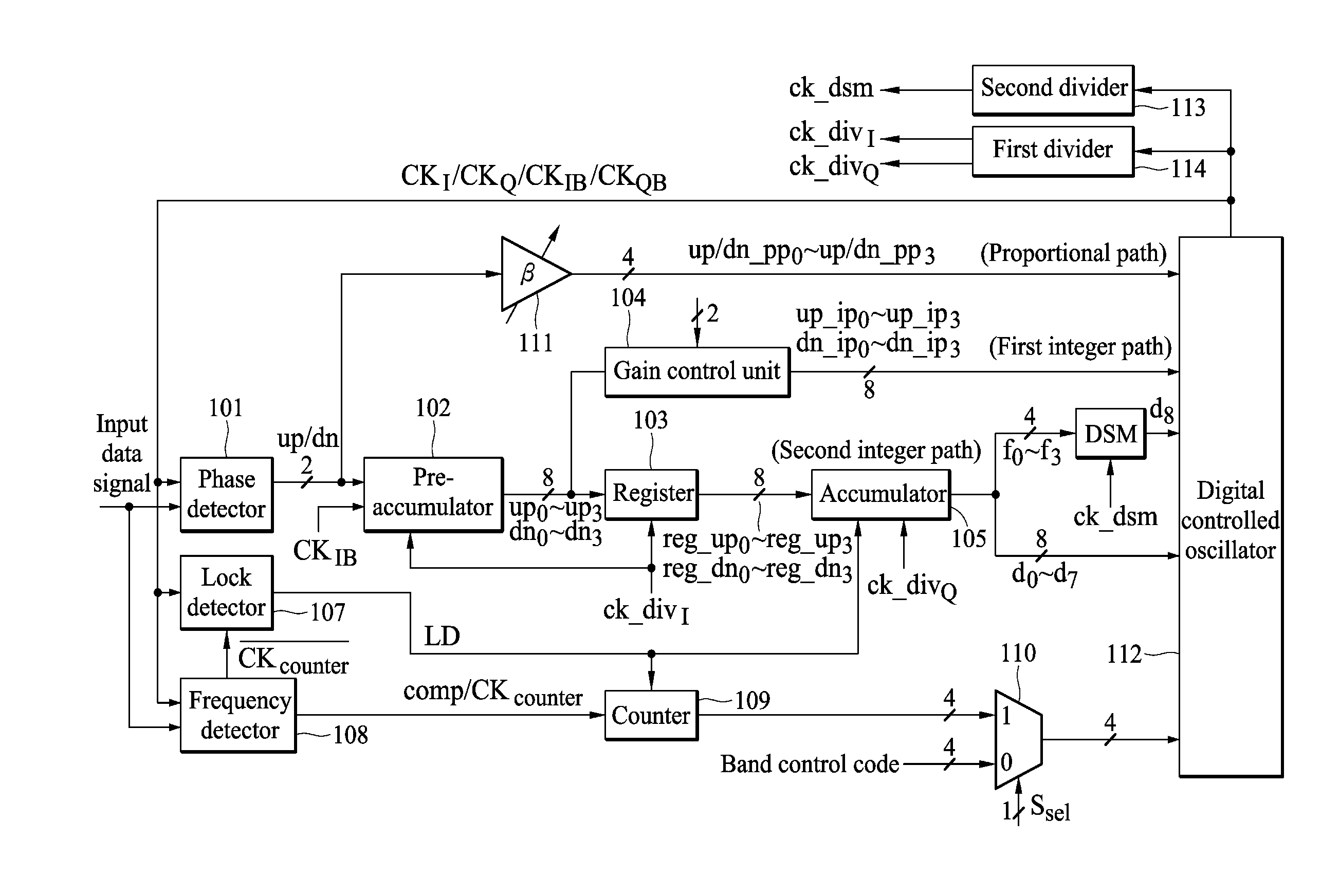
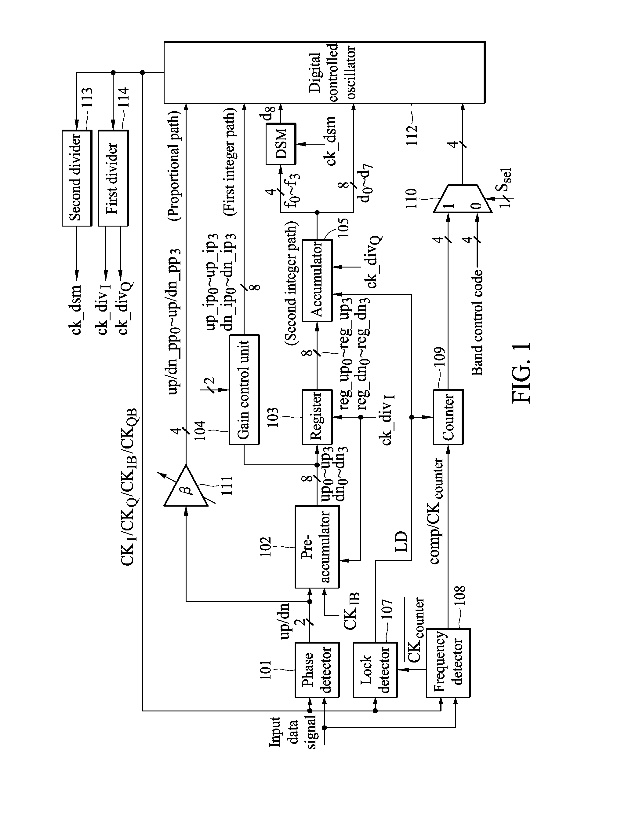
[0022]FIG. 1 is a schematic diagram of an embodiment of a clock and data recovery circuit according to the invention. The clock and data recovery circuit first uses the frequency detector 108 to lock a frequency to ensure that the output clock signal of the digital controlled oscillator 112 is near to a frequency of the input data. The frequency detector 108 receives and compares the output clock signal of the digital controlled oscillator 112 with the frequency of the input data and outputs a comparison result and a count clock signal. In FIG. 1, the output clock signals of the digital controlled oscillator 112 are labeled as CKI, CKQ, CKIB and CKQB, wherein the clock...


PUM


Abstract

An embodiment of the invention provides a clock and data recovery circuit. The clock and data recovery circuit comprises a phase detector, a pre-accumulator, a register, an accumulator and a digital controlled oscillator. By using the transmission path formed by the pre-accumulator, the output of the phase detector can be transmitted to the digital controlled oscillator in advance to adjust the frequency of its output clock signal and the latency due to the accumulator can be reduced.

Description

CROSS REFERENCE TO RELATED APPLICATIONS[0001]This Application claims priority of Taiwan Patent Application No. 098115790, filed on May 13, 2009, the entirety of which is incorporated by reference herein.BACKGROUND OF THE INVENTION[0002]1. Field of the Invention[0003]The present invention relates to a clock and data recovery circuit, and in particular relates to an all digital clock and data recovery circuit.[0004]2. Description of the Related Art[0005]Demand for large off-chip IO bandwidth requires many serial links on a chip. The serial links need to be low-powered, compatible to different technologies, and operate reliably in noisy environments. One example of a serial link component is a clock and data recovery (CDR) circuit.[0006]While analog CDR circuits have good performance, it takes time for analog CDR circuits to be ported to different technology. For a digital CDR circuit, it is insusceptible to leakage, does not need the passive elements, and prohibits quick production-le...

Claims


Application Information

Patent Timeline
IPC IPC(8): H03L7/099
CPCH03L7/0895H03L7/0802
Inventor CHEN, I-FONGLIU, SHEN-IUAN
Owner NAT TAIWAN UNIV
Why Eureka
Try Eureka