Slot antenna

a slot antenna and antenna technology, applied in the direction of slot antennas, antenna details, antennas, etc., can solve the problems of deteriorating the communication performance of portable wireless terminals, hand or human body damage, etc., to prevent mismatching, shorten the distance, and improve the impedance

Inactive Publication Date: 2010-11-18
NEC CORP
View PDF5 Cites 18 Cited by
  • Summary
  • Abstract
  • Description
  • Claims
  • Application Information

AI Technical Summary

Benefits of technology

[0010]The present invention can prevent mismatching through improving the impedance generated because the antenna element comes closer to the reflector, so that the antenna can be formed thin by shortening the distance between the antenna element and the reflector.BEST MODES FOR CARRYING OUT THE INVENTION
[0011]An exemplary embodiment of the invention will be described hereinafter by referring to the drawings.
[0012]As shown in FIG. 1-FIG. 15, a slot antenna according to the exemplary embodiment of the invention includes, as a basic structure: an antenna element 2 having an aperture slit shaped slot 1; a reflector 3 disposed by opposing to the antenna element 2; a feeding device 4 which is electrically and physically connected to the antenna element 2 and the reflector 3; and a short-circuiting device 5 which electrically short-circuits the antenna element 2 and the reflector 3. To electrically and physically connect means that the feeding device 4 is mechanically connected to the antenna element 2 and the reflector 3 and, while keeping that coupled state, the feeding device 4 is electrically connected to be conductive to the antenna element 2 and the reflector 3.
[0013]In a case of a transmitting antenna, the feeding device 4 functions as a power feeding terminal which feeds power to the antenna element 2 and the reflector 3 for sending transmission signals. In a case of a receiving antenna, the feeding device 4 functions as a power receiving terminal which takes in electric currents that are induced on the antenna by the incoming electromagnetic waves.
[0014]With the related slot antenna having the reflector, the impedance of the antenna is deteriorated when the distance between the antenna element and the reflector is shortened for thinning the antenna. This causes mismatching with a wireless circuit, so that it becomes difficult to perform transmission / reception with high efficiency.
[0015]In the exemplary embodiment of the invention, the antenna element 2 and the reflector 3 are electrically short-circuited by the short-circuiting device 5. Thus, the impedance of the antenna can be increased by the short-circuiting device 5. As a result, transmission / reception can be performed with high efficiency by overcoming the mismatching with the wireless circuit to which the feeding device 4 is connected.

Problems solved by technology

As the portable wireless terminals become thinner, the antennas loaded on the portable wireless terminals become susceptible to the external factors such as hands or human bodies because the distance between the antenna and the external factors becomes close when the portable wireless terminals are in use.
This results in causing deterioration in the communication performance of the portable wireless terminals, particularly the deterioration of the antenna characteristic during communications, due to deterioration in the antenna characteristic.

Method used


Image

  • Slot antenna
  • Slot antenna
  • Slot antenna

Examples


example 1

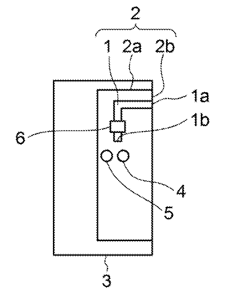
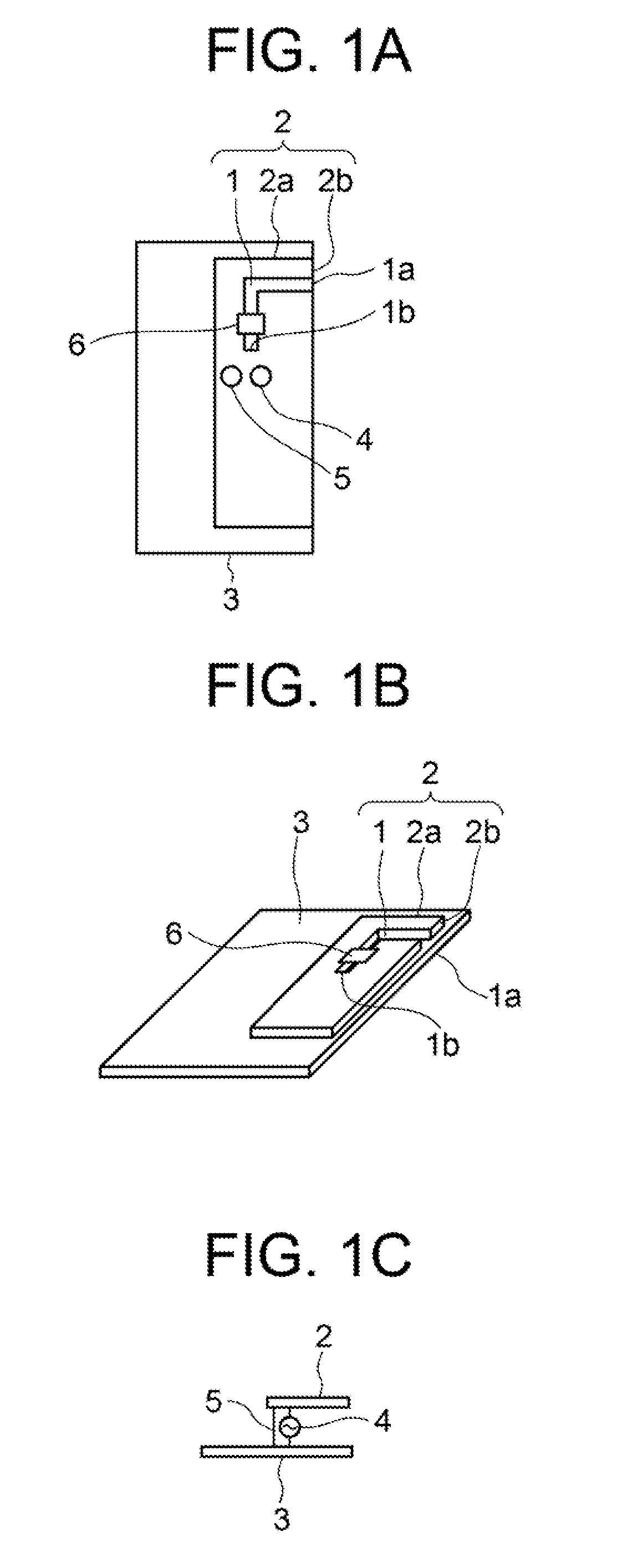
[0019]As shown in FIG. 1A, FIG. 1B, and FIG. 1C, EXAMPLE 1 of the present invention includes an antenna element 2 having an aperture slit shaped slot 1, a reflector 3, a feeding device 4, and a short-circuiting device 5.

[0020]As shown in FIG. 1A and FIG. 1B, the antenna element 2 is obtained by forming the slot 1 to a metal-made flat type emission plate 2a. The slot 1 is an aperture slit shape having an electric length which corresponds to a quarter wavelength of the frequency to be used. An opening end 1a of the slot 1 is opened at an end 2b of the emission plate 2a, and a short-circuit end 1b of the slot 1 is disposed on the inner side than the end 2b of the emission plate 2. While the slot 1 of EXAMPLE 1 is formed in an L-letter shape, the present invention is not limited only to such case. That is, the slot 1 may be in any shapes as long as it is in the shape in which electric fields are concentrated at the opening end 1a of the slot 1.

[0021]As shown in FIG. 1A and FIG. 1B, the ...

example 2

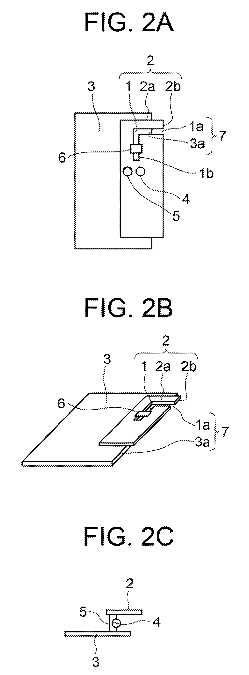
[0034]EXAMPLE 2 shown in FIG. 2 is a modification of EXAMPLE 1 shown in FIG. 1, in which an adjuster 7 for reducing the reactance component of the antenna is employed.

[0035]As shown in FIG. 2A, FIG. 2B, and FIG. 2C, the adjuster 7 of EXAMPLE 2 is structured to reduce the reactance component for the slot 1 by having the end 2b where the opening end 1a of the slot 1 in the antenna element 2 is formed projected towards the outer side with respect to the end 3a of the reflector 3. Other structures are the same as those of EXAMPLE 1.

[0036]In EXAMPLE 2, the end 2b of the antenna element 2 is disposed by being shifted towards the outer side with respect to the reflector 3. Therefore, the reactance component of the antenna can be decreased and the antenna band can be expanded. Particularly, the effects thereof become conspicuous by shifting the end 2b of the antenna element 2 where the opening end 1a of the slot 1 in which the strong electric field components are concentrated is provided to...

example 3

[0039]The slot is structured as a single-resonance type slot in EXAMPLE 1 shown in FIG. 1, whereas the slot is structured as a double-resonance type slot in EXAMPLE 3 shown in FIG. 3.

[0040]As shown in FIG. 3A, FIG. 3B, and FIG. 3C, in EXAMPLE 3, a slot 1′ of the same structure as that of the slot 1 is added, and the frequency switching devices 6, 6 are provided to the slots 1, 1′, respectively. The slot 1 and the slot 1′ configuring the double-resonance type slots are formed in different lengths. Further, the feeding device 4 and the short-circuiting device 5 are provided in common for the double-resonance type slots 1, 1′. Other structures including the opening end 1a′ and the short-circuit end 1b′ of the slot 1 are the same as those of EXAMPLE 1.

[0041]The two slots 1 and 1′ in different lengths are provided to the antenna element 2 in EXAMPLE 3, so that it is possible to have resonance at frequencies depending on each of the slot lengths. Therefore, it is possible to achieve a wid...


PUM


Abstract

To realize an antenna made thinner. A slot antenna includes: an antenna element having an aperture slit shaped slot; a reflector disposed by being opposed to the antenna element; a feeding device which is electrically and physically connected to the antenna element and the reflector; a short-circuiting device which electrically short-circuits the antenna element and the reflector; and a frequency switching device, which is provided on the slot, for switching resonance frequencies of the slot. The impedance generated by the approach between the antenna element and the reflector can be improved to prevent mismatching and the distance therebetween can be reduced to make an antenna thinner.

Description

TECHNICAL FIELD[0001]The present invention relates to a slot antenna having a reflector. More specifically, the present invention relates to a thin-type slot antenna which enables operations with a plurality of frequency bands.BACKGROUND ART[0002]Recently, portable wireless terminals have been required to be thin and to have a connecting function to various wireless networks. Accordingly, there has been an increasing demand for the antenna loaded on the portable wiring terminal to be thin because of limited mounting space and demand for corresponding to multibands required for being connected to various kinds of wireless services.[0003]As the portable wireless terminals become thinner, the antennas loaded on the portable wireless terminals become susceptible to the external factors such as hands or human bodies because the distance between the antenna and the external factors becomes close when the portable wireless terminals are in use. This results in causing deterioration in the ...

Claims


Application Information

Patent Timeline
Patent Type & Authority Applications(United States)
IPC IPC(8): H01Q13/10H01Q5/00H01Q5/10H01Q5/364H01Q19/10
CPCH01Q1/243H01Q3/24H01Q9/0421H01Q5/364H01Q13/10H01Q19/10H01Q9/14
Inventor TAURA, TORU
Owner NEC CORP
Why Eureka
Try Eureka