3D Display Device with Controllable Device for Tracking Visibility Regions

a display device and visibility region technology, applied in the field of three-dimensional representation of the 3d scene, can solve the problems of low brightness efficiency, large demands on coherence and representation quality, and inability to generate light waveguide types

Inactive Publication Date: 2010-11-18
SEEREAL TECHNOLOGIES
View PDF2 Cites 99 Cited by
  • Summary
  • Abstract
  • Description
  • Claims
  • Application Information

AI Technical Summary

Benefits of technology

[0049]The display device according to this invention combines in a controllable tracking device the possibilities of the prior art for generating output coupling points such that the individual advantages are combined and the drawbacks are circumvented or avoided.

Problems solved by technology

However, the larger the diagonal of a controllable spatial light modulator (SLM), the greater the demands made on the coherence and representation quality in the holographic display device.
However, a great disadvantage of such a display device is the very low efficiency in respect to brightness, because the backlight must continuously supply a constant luminous intensity across the entire surface of the shutter panel, while those pixels of the shutter panel which are not switched to the transmissive mode absorb a large portion of the light.
This type of light waveguide is not suited for generating a plane wave field which is meant to illuminate an SLM and e.g. to generate a holographic reconstruction.
However, using birefringent materials such as liquid crystals has the disadvantage that the effective refractive index also depends on the angle under which the light hits the interface of the two materials.

Method used


Image

  • 3D Display Device with Controllable Device for Tracking Visibility Regions
  • 3D Display Device with Controllable Device for Tracking Visibility Regions
  • 3D Display Device with Controllable Device for Tracking Visibility Regions

Examples


first embodiment

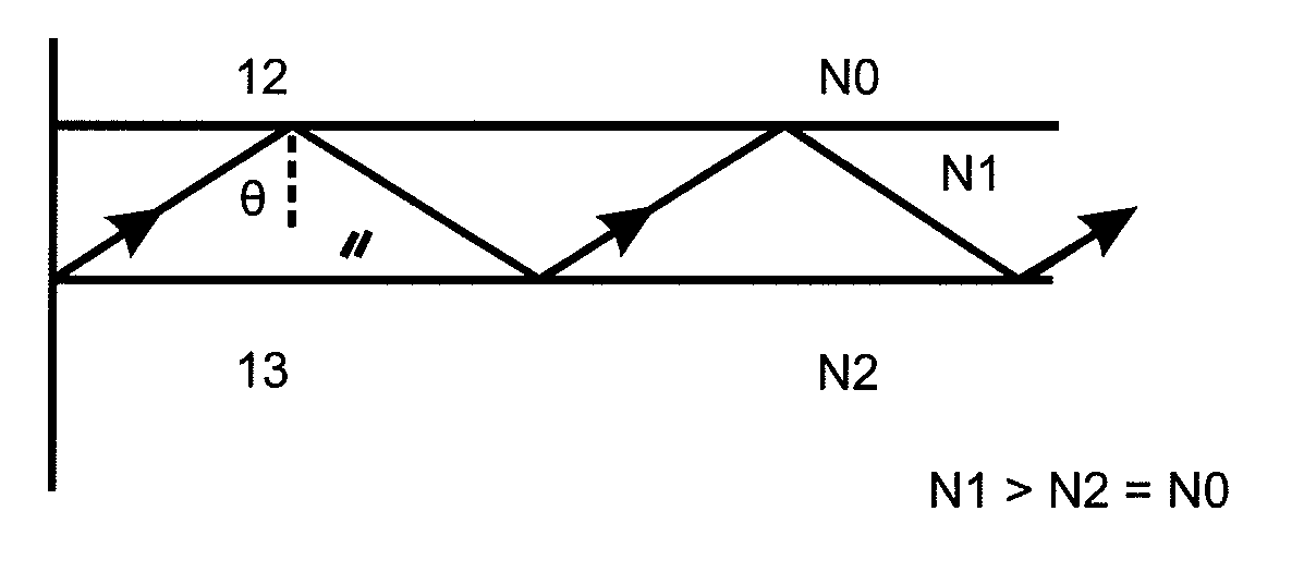
[0068]A thus designed waveguide forms the basis for a display device according to this invention, with which a device for tracking light and thus for tracking a visibility region generated by that light can be realised when the observer moves laterally and / or horizontally.

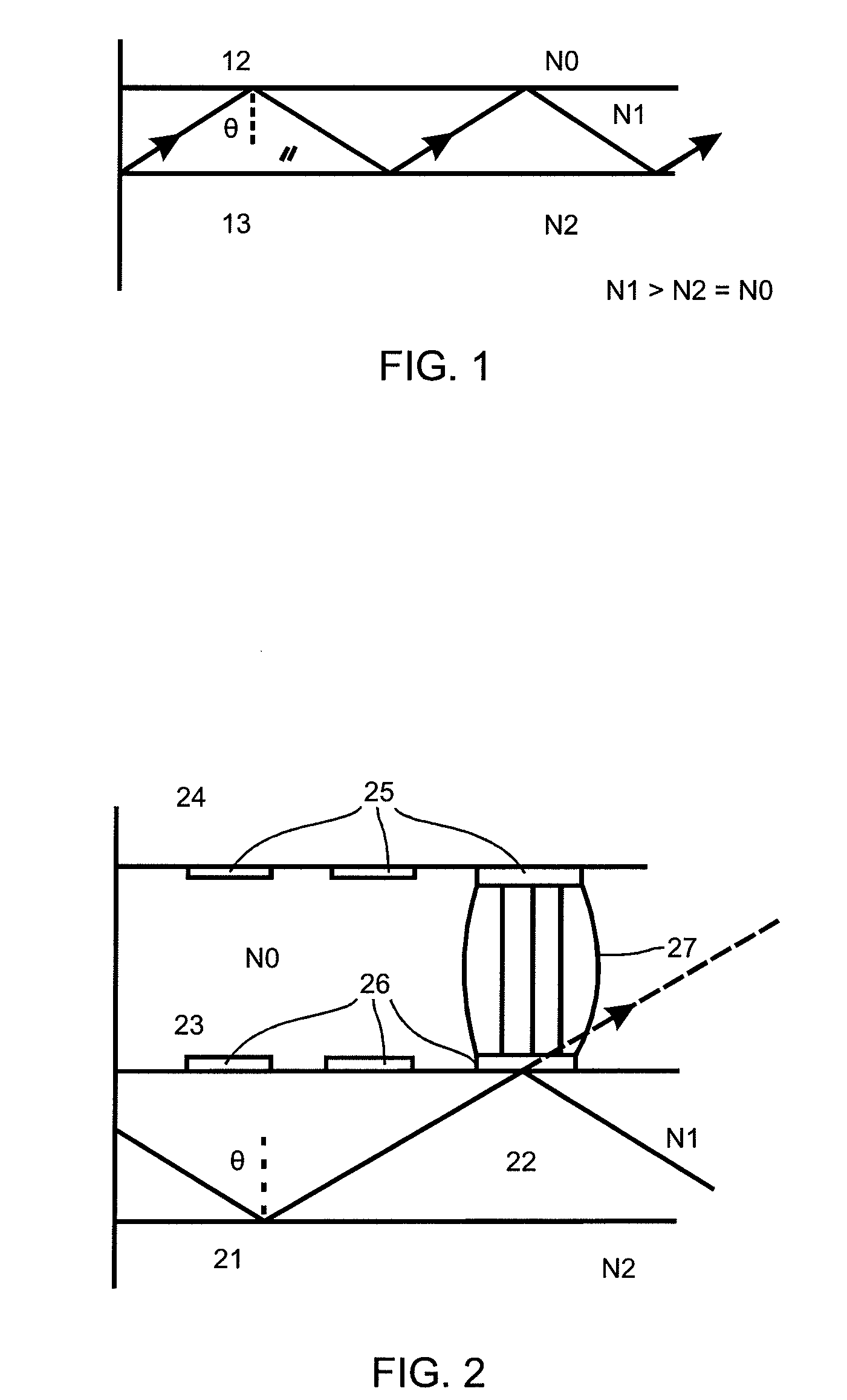
[0069]The tracking device in the display device has the following function: The LC layer with the birefringent material is connected with spatially structured, transparent control electrodes. The control electrodes are arranged on at least one face of the LC layer as a matrix or in stripes in the cladding, thus defining potential output coupling points in the LC layer. A continuous electrode is disposed on the other face of the LC layer, very much like in conventional LC display panels. If a voltage is applied to at least one control electrode, then the total reflection is cancelled between this electrode and the opposite electrodes in this position in the matrix or striped arrangement of control electrodes, thus c...

second embodiment

[0080]This principle forms the basis of a second embodiment according to this invention of the display device with a controllable tracking device, which serves to illuminate a SLM and to generate a visibility region. This embodiment will be described in more detail below.

[0081]An arrangement of droplets of one liquid in a second liquid forms the cladding of a waveguide.

[0082]The refractive index difference between the cladding and the core is adjusted by choosing liquids with a suitable refractive index such that the total reflection is only cancelled in the region of the droplet, so that an output coupling point is generated there and that light can leave the waveguide. The displacement of the droplet does thus not serve to turn a pixel on or off, as in [3], but to move an output coupling point from an old to a new position.

[0083]In contrast to the prior art, electrodes are not combined in pairs to form a pixel, but each individual electrode of a matrix or striped arrangement defin...

third embodiment

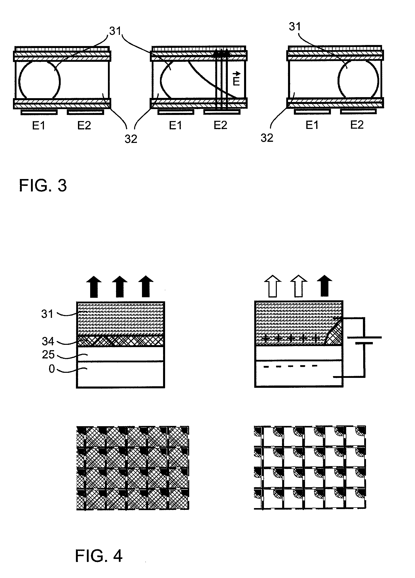
[0100]According a third embodiment according to this invention of the display device, variable output coupling points can be created by switching on and off the control electrodes in application of this principle.

[0101]Like in the first embodiment, the electrodes can be arranged in a matrix or in stripes in the waveguide, so that the output coupling points exhibit an according pattern. An output coupling point is turned on by applying a voltage to one of the electrodes.

[0102]The dielectric 25 of the EW cells can serve as the core of the waveguide, as described above. Alternatively, the dielectric can be a very thin layer disposed between the core and the liquids.

[0103]Deviating from the prior art described above, the oil 34 is not absorbing, but transparent. However, the chemical composition of the oil is chosen such that it has a lower refractive index than the core of the waveguide, so that total reflection occurs between the core and the oil in this arrangement.

[0104]If the oil f...


PUM


Abstract

A 3D display device with controllable device for tracking visibility regions is disclosed, and includes a controllable device for tracking a visibility region, generated by way of superposition of light source images, in a observer plane of the display device. In preferred embodiments, the cladding of a waveguide comprises at least one material with optical properties of an anisotropic liquid, or at least two materials with optical properties of an isotropic liquid; a matrix arrangement of control electrodes defines multiple positions to be generated for local exit points in the cladding of the waveguide at which the total reflection is locally cancelled; and a system controller modifies positions of the output coupling points for superposing the output-coupled light through the lens array to the visibility region by displacing an output coupling point, or by switching off one output coupling point and switching on another one.

Description

CROSS-REFERENCE TO RELATED APPLICATIONS[0001]This application is based on and claims priority to German Application No. DE 10 2009 003 069.7, filed May 13, 2009, the entire contents of which are fully incorporated herein by reference.BACKGROUND OF THE INVENTION[0002]The present invention relates to a display device for three-dimensional representation of a 3D scene, which is visible for an observer eye from at least one visibility region. The display device includes a controllable device for tracking the at least one visibility region in an observer plane of the display device, where the main component of said tracking device is based on a controllable optical waveguide. The display device further comprises a controllable spatial light modulator (SLM) with a pixel matrix for modulating the light, and a system controller unit for controlling the electrode arrangement. The tracking device comprises at least one light source which emits light, the controllable waveguide for guiding the...

Claims


Application Information

Patent Timeline
Patent Type & Authority Applications(United States)
IPC IPC(8): H04N13/00G03H1/12G02B30/27
CPCG02B26/005G02B27/2214G03H1/22G03H2223/16G03H1/2294G03H2222/34G03H1/2286G03H2226/05G02B30/27
Inventor LEISTER, NORBERT
Owner SEEREAL TECHNOLOGIES
Why Eureka
Try Eureka