Optical element and display device using the same

a technology of optical elements and display devices, applied in the field of optical elements, can solve the problems of deteriorating image quality and lowering the transmittance of light, and achieve the effect of avoiding deterioration of image quality

Active Publication Date: 2010-11-18
PANASONIC LIQUID CRYSTAL DISPLAY CO LTD +1
View PDF8 Cites 70 Cited by
  • Summary
  • Abstract
  • Description
  • Claims
  • Application Information

AI Technical Summary

Benefits of technology

[0017]Also, the present invention is to realize a view angle limiting element capable of obtaining higher transmittance for light when the view angle limiting element is applied to a liquid crystal display element.
[0040]It then becomes possible to provide the optical element, or the display device using this optical element, which limit transmissions of light at a predetermined azimuth angle and in a predetermined polar angle range, while the view angle is controlled. Further, even when this optical element is combined with such a display element as a liquid crystal display panel, there is no deterioration of the image quality caused by moire.

Problems solved by technology

As a result, the louver film owns the following problem.
That is, moire may occur between a pixel array of display elements and the periodic structure of the louver film, so that an image quality is deteriorated.
Further, since the louver film is equipped with the optical absorption layer, this louver film owns another problem that a portion of light is absorbed by the optical absorption layer even along a front plane direction, so that transmittance for light is lowered.

Method used


Image

  • Optical element and display device using the same
  • Optical element and display device using the same
  • Optical element and display device using the same

Examples


embodiment 1

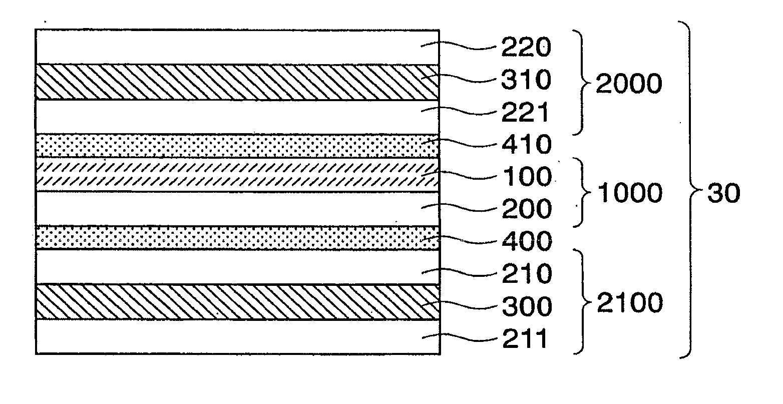
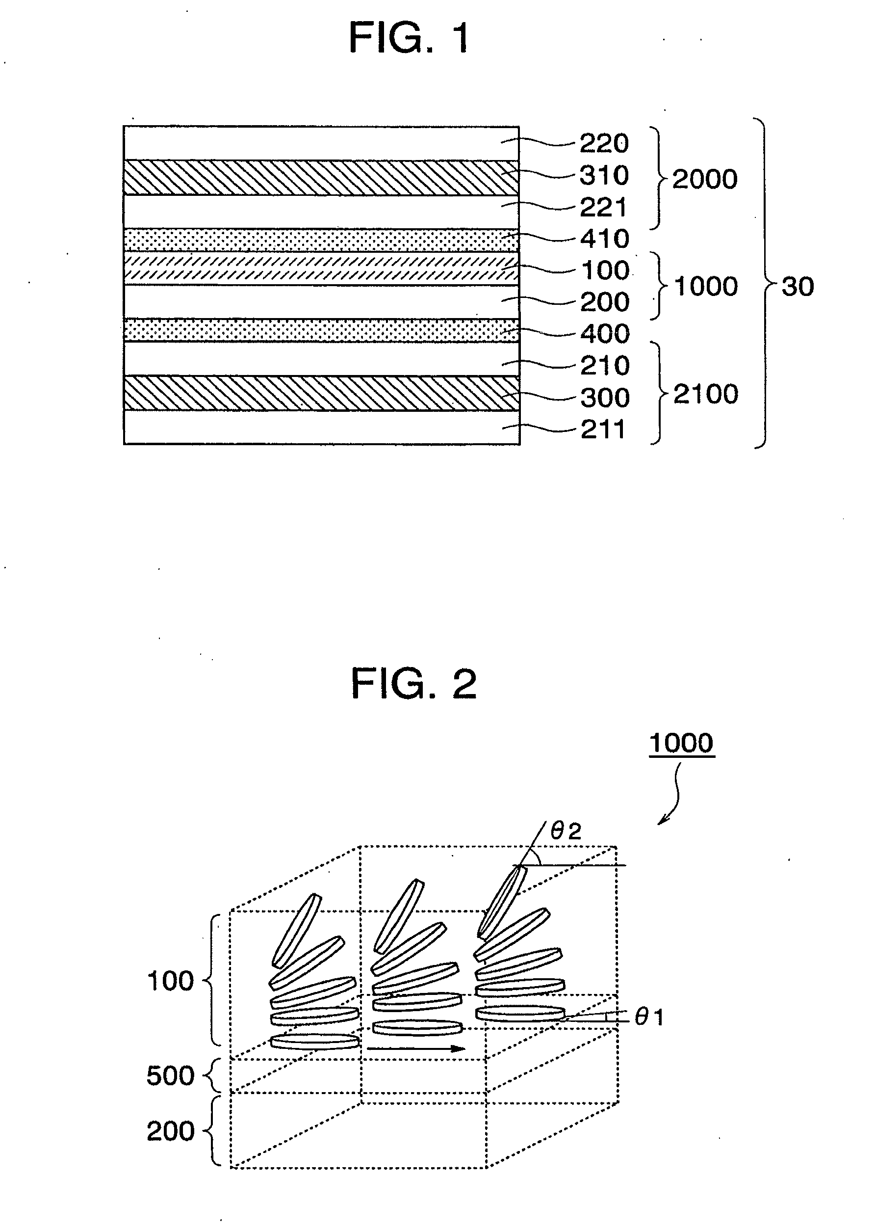
[0086]FIG. 1 is a sectional view for indicating a portion of an optical element according to an embodiment 1 of the present invention. This optical element is capable of reducing an amount of light transmittance in specific azimuth and a specific view angle range. In the case that the above-described optical element is employed in a display device, this optical element is capable of limiting a view angle within which an image on a screen attached to the element can be seen by an operator. In this specification, an optical element having such a function will be referred to as a “view angle limiting element” hereinafter.

[0087]A view angle limiting element 30 of the embodiment 1 is constructed in such a manner that a liquid crystal film 1000 containing a discotic liquid layer 100 is stacked between a first polarizing film 2000 and a second polarizing film 2100.

[0088]A polarizer transmits therethrough one of linearly polarized light components within light entered to the own polarlizer,...

embodiment 2

[0111]Next, a description is made of a display device according to an embodiment 2 of the present invention. FIG. 5 is a sectional view for partially showing a schematic structure of the display device according to the embodiment 2 of the present invention.

[0112]This display device is constituted by a liquid crystal display panel 10, an illuminating device 20 arranged on a rear surface of this liquid crystal display panel 10, and a view angle limiting element 30. This view angle limiting element 30 has been explained in the previous embodiment 1, and is arranged between the liquid crystal display panel 10 and the illuminating device 20.

[0113]The illuminating device 20 illuminates a display region of the liquid crystal display panel 10 from the rear surface side thereof. As the illuminating device 20, there are an edge light type (light guide type), a just-directly under type (reflection plate type), a plane-shaped light source type, and the like. As this illuminating device 20, an o...

embodiment 3

[0151]Next, a description is made of a display device according to another embodiment 3 of the present invention. FIG. 12 is a sectional view for partially showing a schematic structure of the display device according to this embodiment 3 of the present invention.

[0152]This display device is constituted by a liquid crystal display panel 10, an illuminating device 20 arranged on a rear surface of this liquid crystal display panel 10, and a view angle limiting element 31. This view angle limiting element 31 is arranged between the liquid crystal display panel 10 and the illuminating device 20.

[0153]The display device of this embodiment 3 is featured by that in the above-described embodiment 2 explained with reference to FIG. 5, a reflection type polarizing film is newly provided with the view angle limiting element 31. As a result, the same reference numerals shown in the above-described embodiment will be employed as those for denoting the same optical elements, and thus, detailed de...


PUM

PropertyMeasurementUnit
angleaaaaaaaaaa
angleaaaaaaaaaa
angleaaaaaaaaaa

Abstract

An optical element is arranged in such a manner that a screen thereof can be hardly observed from a predetermined direction, and a deterioration of an image quality caused by moire does not occur. The optical element is constituted by a first polarizing layer, a second polarizing layer, and a liquid crystal layer arranged between these two polarizing layers. In the optical element, absorption axes of the first polarizing layer and the second polarizing layer are located parallel to each other; the liquid crystal layer is made of hybrid-aligned discotic liquid crystal; and an alignment axis of the liquid crystal layer is located parallel to, or perpendicular to both absorption axes of the first polarizing layer and of the second polarizing layer.

Description

CLAIM OF PRIORITY[0001]This application is a divisional of application Ser. No. 11 / 271,802, filed on Nov. 14, 2005, now allowed, which claims the benefit of Japanese Application No. 2004-329941, filed Nov. 15, 2004 in the Japanese Patent Office, the disclosures of which are incorporated herein by reference.BACKGROUND OF THE INVENTION[0002]1. Field of the Invention[0003]The present invention relates to an optical element capable of varying view angles of a screen in display device, and a display device equipped with such optical element.[0004]2. Description of the Related Art[0005]As to screens of display devices, wide view angles are required which are effective in such a case that these screens are observed by a large number of viewers, and in contrast, narrow view angles are required in order that contents of screens are peeped by a third party, namely, various conditions are required for these screens of the display devices in response to use circumstances thereof.[0006]As optica...

Claims


Application Information

Patent Timeline
Patent Type & Authority Applications(United States)
IPC IPC(8): G02F1/1335
CPCG02F1/1323G02F1/13471G02F1/133632G02F1/133524G02F1/1335G09F9/35G02F1/133
Inventor ADACHI, MASAYAITOU, OSAMUKOMURA, SHINICHI
Owner PANASONIC LIQUID CRYSTAL DISPLAY CO LTD
Why Eureka
Try Eureka