Control channel signaling using code points for indicating the scheduling mode

a control channel and code point technology, applied in the field of control channel signals, to achieve the effect of simplifying the rate matching of the control channel and reducing the number of different control channel sizes

Active Publication Date: 2010-11-18
PANASONIC INTELLECTUAL PROPERTY CORP OF AMERICA
View PDF8 Cites 73 Cited by
  • Summary
  • Abstract
  • Description
  • Claims
  • Application Information

AI Technical Summary

Benefits of technology

[0037]One benefit that can be achieved by using code points is the avoidance of flag fields which indicate the scheduling mode or the format of the control channel. This reduces the size of the control channel and, therefore, the signalling overhead.
[0039]Further, the use of different scheduling schemes also increases the flexibility in control channel signalling so that the control channel overhead may be reduced. For example, there may be two different scheduling modes defined, wherein one of the scheduling modes only signals control channel information for retransmissions of a protocol data packets (in contrast to providing a control channel signal for each protocol data unit transmission—which could be the case for the other, second scheduling mode). This exemplary scheduling mode may for example be advantageous for the transmission of user data of delay-sensitive services, where the (average) user data size of a protocol data unit is small in comparison to other service types.
[0041]In one variation the number of bits of the control channel signal is equal for at least two scheduling modes. This may be for example advantageous to simplify the rate matching for the control channels or to reduce the number of different control channel sizes a mobile station has to decode.

Problems solved by technology

Which parts of the L1 / L2 control information is signaled on the uplink and which proportion is signaled on the downlink is typically a design issue and depends on the view how much control should be carried out by the network and how much autonomy should be left to the mobile station.

Method used


Image

  • Control channel signaling using code points for indicating the scheduling mode
  • Control channel signaling using code points for indicating the scheduling mode
  • Control channel signaling using code points for indicating the scheduling mode

Examples


Embodiment Construction

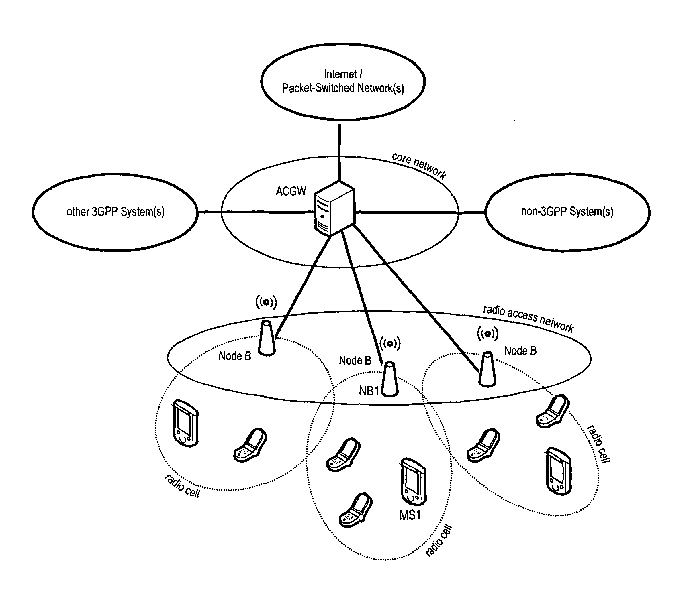
[0076]The following paragraphs will describe various embodiments of the invention. For exemplary purposes only, most of the embodiments are outlined in relation to an (evolved) UMTS communication system according to the SAE / LTE discussed in the Technical Background section above. It should be noted that the invention may be advantageously used for example in connection with a mobile communication system such as the SAE / LTE communication system previously described or in connection with multi-carrier systems such as OFDM-based systems, but the invention is not limited to its use in this particular exemplary communication network.

[0077]Before discussing the various embodiments of the invention in further detail below, the following paragraphs will give a brief overview on the meaning of several terms frequently used herein and their interrelation and dependencies. Generally, a protocol data unit may be considered a data packet of a specific protocol layer that is used to convey one or...


PUM


Abstract

The invention relates to a control channel signal for use in a mobile communication system providing at least two different scheduling modes. Further the invention relates to a scheduling unit for generating the control channel signal and a base station comprising the scheduling unit. The invention also relates to the operation of a mobile station and a base station for implementing a scheduling mode using the control channel signal proposed by the invention. In order to facilitate the use of different scheduling schemes for user data transmission while avoiding an additional flag for indicating the scheduling mode in the control signaling, the invention proposes the use of code points in existing control channel signal fields. Further, the invention proposes a specific scheduling mode for use in combination with the proposed new control channel signal according to the invention. According to this scheduling mode control channel information is only provided for retransmissions, while initial transmissions are decoded using blind detection.

Description

FIELD OF THE INVENTION[0001]The invention relates to a control channel signal for use in a mobile communication system providing at least two different scheduling modes. Further, the invention relates to a scheduling unit for generating the control channel signal and a base station comprising the scheduling unit. The invention also relates to the operation of a mobile station and a base station for implementing a scheduling mode using the control channel signal proposed by the invention.TECHNICAL BACKGROUNDPacket-Scheduling and Shared Channel Transmission[0002]In wireless communication systems employing packet-scheduling; at least part of the air-interface resources are assigned dynamically to different users (mobile stations—MS or user equipments—UE). Those dynamically allocated resources are typically mapped to at least one Physical Uplink or Downlink Shared CHannel (PUSCH or PDSCH). A PUSCH or PDSCH may for example have one of the following configurations:[0003]One or multiple co...

Claims


Application Information

Patent Timeline
Patent Type & Authority Applications(United States)
IPC IPC(8): H04W72/12
CPCH04L1/0027H04L1/0028H04L1/0038H04L1/1867H04L5/0094H04L5/0003H04L5/0014H04L5/0037H04L1/1896H04W72/0446H04W72/23H04W72/21H04W72/20H04L1/1854H04L1/1861H04L1/1864H04L1/1812H04L5/0055H04W72/12H04W72/04
Inventor WENGERTER, CHRISTIAN
Owner PANASONIC INTELLECTUAL PROPERTY CORP OF AMERICA
Why Eureka
Try Eureka