Anesthetic Vaporizer Filling System

a technology of anesthetic vaporizer and filling system, which is applied in the direction of respirator, liquid handling, packaging goods type, etc., can solve the problems of reducing attentiveness, reducing reaction time, exposing the personnel around the vaporizer, waste or loss of anesthetic agents, etc., and achieves the effect of increasing distan

Active Publication Date: 2010-11-25
GENERAL ELECTRIC CO
View PDF8 Cites 7 Cited by
  • Summary
  • Abstract
  • Description
  • Claims
  • Application Information

AI Technical Summary

Benefits of technology

[0007]An adapter apparatus for connection between an anesthetic bottle and an anesthetic vaporizer is further disclosed herein. An embodiment of the adapter includes a bottle cap configured at one end for connection to an anesthetic bottle. The bottle cap includes an open interior. An adapter includes a bottle end and vaporizer end, the bottle end terminates in a sealing surface that couples with the bottle cap to form a fluid seal. The vapori

Problems solved by technology

Further, inhalation of vapor by healthcare personnel in an area near where the anesthetic agent is being used can cause drowsiness, reduced attentiveness, and/or reduced reaction time.
Leakage of anesthetic liquids or vapors from the sump may result in exposing the personnel around the vaporizer t

Method used


Image

  • Anesthetic Vaporizer Filling System
  • Anesthetic Vaporizer Filling System
  • Anesthetic Vaporizer Filling System

Examples


embodiment 50

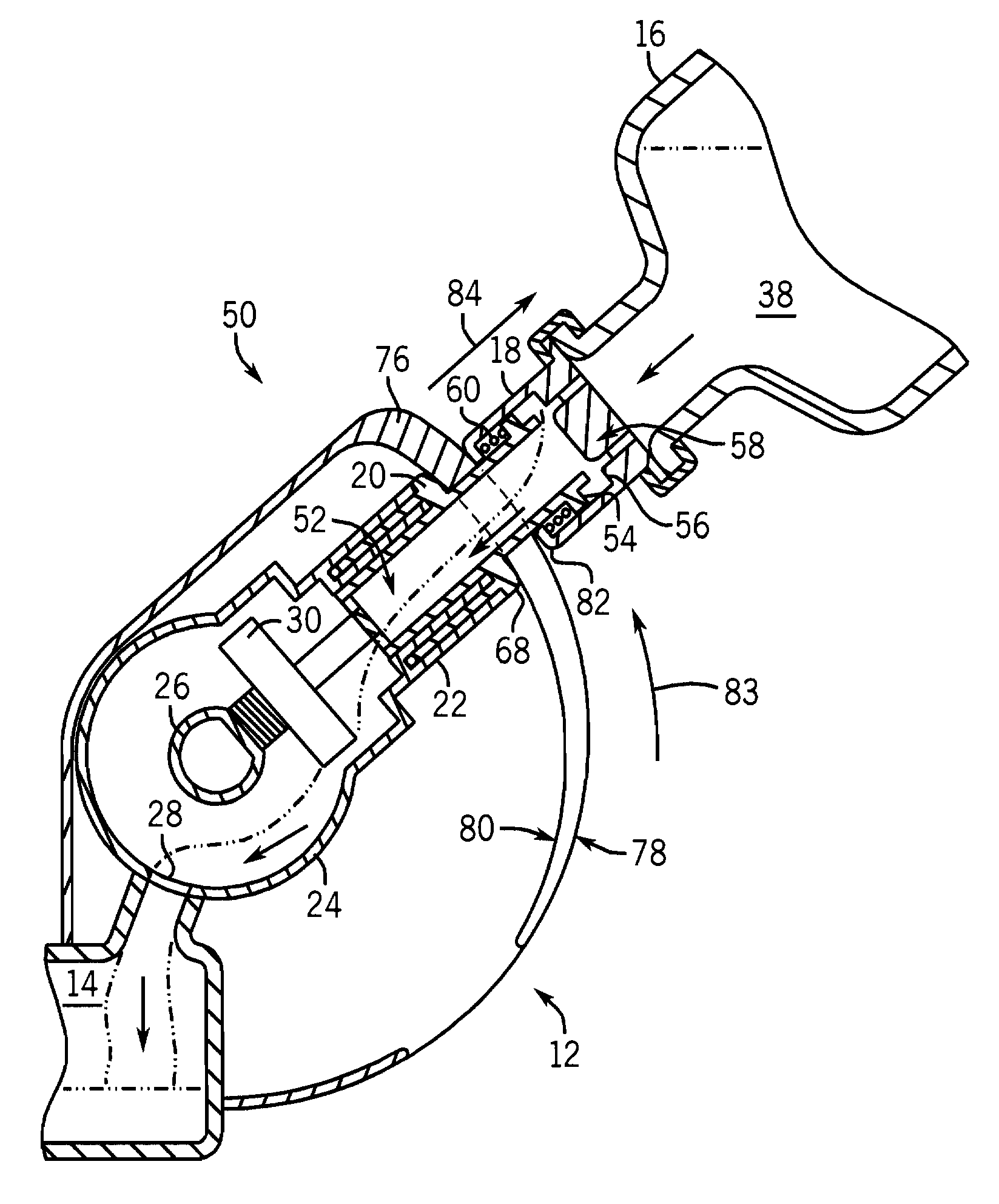
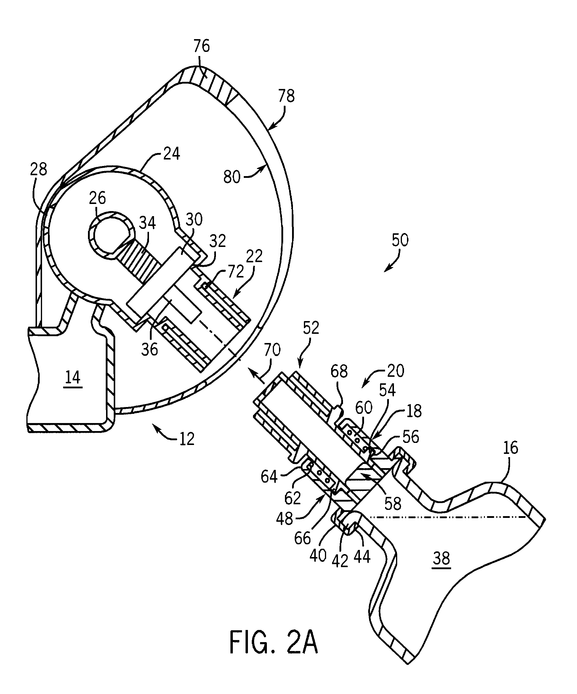
[0018]FIGS. 2A-C depict an embodiment 50 of the system for delivery of a liquid anesthetic agent to an anesthetic vaporizer. It should be noted that in the figures like numerals are used to reference similar components common among the embodiments disclosed herein.

[0019]Referring to FIG. 2A, the system 50 includes the vaporizer filling system 12 of the vaporizer (not depicted). The vaporizer filling system 12 includes a sump 14 and a filler spout 22. The filler spout 22 is connected to the sump 14 through a filler assembly 24. The filler assembly 24 includes a pivot point 26, about which the filler assembly 24 is able to rotate.

[0020]The filler assembly 24 further includes a sump valve 28. The sump valve 28 controls the fluid communication between the sump 14 and the filler assembly 24. In an embodiment, the filler valve 28 operates as a ball valve such that rotation of the filler assembly 24 about the pivot point 26 moves the filler valve 28 from a sealing position wherein fluid co...

embodiment 100

[0047]FIGS. 3A-C depict a further embodiment 100 of the system for the delivery of a liquid anesthetic agent to an anesthetic vaporizer. As noted previously, like components between the figures are numbered the same such as to maintain consistency between the embodiments.

[0048]The system 100 includes a vaporizer filling system 86 that includes the sump 14, the filler assembly 24, and the filler spout 22. The vaporizer filling system 86 further includes an intermediate connection 88 that is disposed radially interior to the filler spout 22. The intermediate connection 88 is also coaxial to the filler spout 22. The filler spout 22 includes an annular ring 90 that forms a fluid impervious seal between the filler spout 22 and the intermediate connection 88. Alternatively, the filler spout 22 and / or the intermediate connection 88 may comprise a sealing surface on the portions of the filler spout 22 and the intermediate connection 88 that engage each other. This sealing surface of the fil...

embodiment 150

[0059]FIGS. 4A-C depict an embodiment 150 of the system for delivery of a liquid anesthetic agent to an anesthetic vaporizer. It should be noted that in the figures, like numerals are used to reference similar components common among the embodiments.

[0060]Referring to FIG. 4A, this embodiment of the system 150 includes a vaporizer filling system 116 with a sump 14, a filler assembly 24, and a filler spout 22. Fluid communication between the filler assembly 24 and the sump 14 is controlled by a sump valve 28, which may be arranged as a ball-type valve that moves from a sealed position that prevents fluid communication between the filler assembly 24 and the sump 14 and an open position that allows fluid communication between the filler assembly 24 and the sump 14 as the filler assembly 24 is rotated about a pivot point 26.

[0061]The filler assembly 24 further includes a filler valve 118 disposed between the filler assembly 24 and the filler spout 22. The filler valve 118 is movable fro...


PUM

PropertyMeasurementUnit
Forceaaaaaaaaaa
Pressureaaaaaaaaaa
Distanceaaaaaaaaaa

Abstract

A system for the delivery of a liquid anesthetic agent to a sump of an anesthetic vaporizer includes a filler assembly rotatable about a pivot point. The filler assembly further includes a sump valve that controls fluid communication between the filler assembly and the sump. An adapter is coupled with the filler spout and includes a sealing surface that forms a seal against fluid communication between the anesthetic bottle and the adapter. The filler assembly, the filler spout, and the adapter are rotated about the pivot point along the rail. The rotation of the filler assembly, the filler spout, and the adapter about the pivot point opens the sump valve and the seal between the adapter and the anesthetic bottle.

Description

BACKGROUND[0001]The present disclosure generally relates to a system for transferring a liquid anesthetic agent from an anesthetic bottle to an anesthetic vaporizer. More specifically, the present disclosure relates to an anesthetic vaporizer, an adapter for an anesthetic bottle, and anesthetic vaporizer filling system.[0002]Anesthetic agents are typically volatile substances with relatively low boiling points and high vapor pressures. Anesthetic agents can be flammable and explosive in both the liquid and vapor states. Further, inhalation of vapor by healthcare personnel in an area near where the anesthetic agent is being used can cause drowsiness, reduced attentiveness, and / or reduced reaction time. An anesthetic agent is administered to a patient during anesthesia through the use of an anesthetic vaporizer. The anesthetic agent is supplied to the patient as a vapor from a reservoir of anesthetic liquid stored in an internal sump within a vaporizer. The anesthetic agent is typical...

Claims


Application Information

Patent Timeline
IPC IPC(8): B65B3/04A61M16/18
CPCA61M16/183
Inventor RINDY, RYAN W.THAM, ROBERT Q.
Owner GENERAL ELECTRIC CO
Why Eureka
Try Eureka