Photovoltaic electrical energy generating system

a photovoltaic and electrical energy technology, applied in the field of electric power generation systems, can solve the problems of building owners resisting the use of photovoltaic energy generation, limited surface area of roofs, and high installation costs of solar panels incorporating photovoltaic arrays. , to achieve the effect of reducing the number of installation steps, and reducing the cost of installation

Inactive Publication Date: 2010-11-25
CARNATION RICHARD E
View PDF4 Cites 21 Cited by
  • Summary
  • Abstract
  • Description
  • Claims
  • Application Information

AI Technical Summary

Problems solved by technology

Oftentimes, however, a building owner might resist the use of photovoltaics to generate energy for aesthetic reasons and because of the significant cost associated with installing devices which use this technology.
Further, roofs have limited surface areas as they were built not necessarily to capture maximum ambient light energy but to simply act as a secure covering for a structure or dwelling In addition, solar panels incorporating photovoltaic arrays can be expensive to install requiring a skilled applicator and significant dedicated hardware to accomplish the task.
Even when done professionally, such installations can result in roof leakage and structural compromise beyond the fact that, as noted, in residential settings, solar panels are oftentimes considered too “industrial” a look to justify the implementation.

Method used


Image

  • Photovoltaic electrical energy generating system
  • Photovoltaic electrical energy generating system
  • Photovoltaic electrical energy generating system

Examples


Embodiment Construction

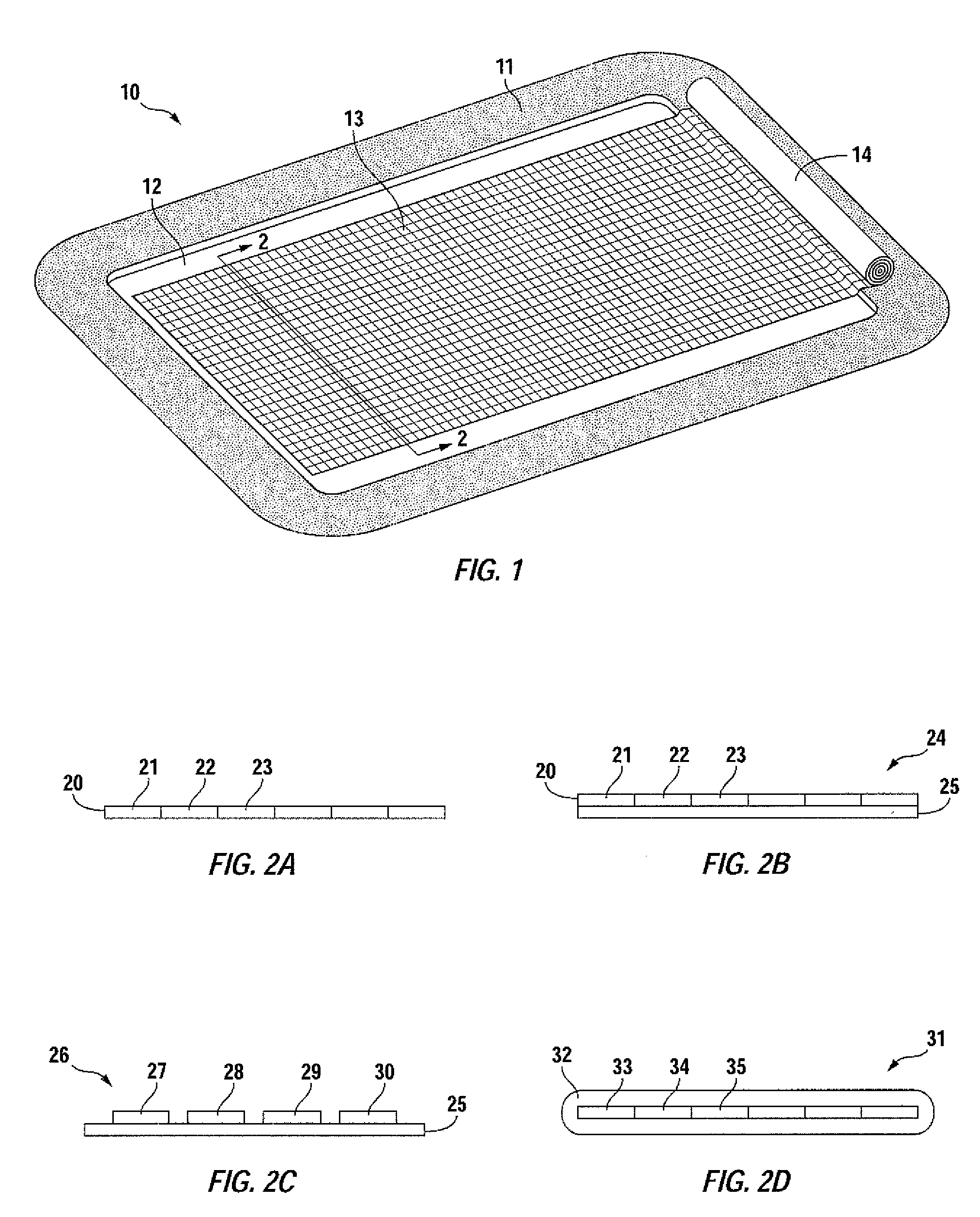
[0014]The present invention involves a system for the generation of electric power for use in connection with a water feature. In turning to FIG. 1, one such water feature is shown in the form of an in ground swimming pool 10 commonly in use both domestically and commercially. Swimming pool 10 is surrounded by walkway 11, generally of concrete or composite material containing water body 12.

[0015]As stated previously, in order to maintain security and safety, increase pool temperature as well as to reduce debris accumulation within water body 12, pool cover 13 is drawn over virtually the entire surface area of pool 10 when the pool is not in use. Under ordinary circumstances, cover 13 is of a plastic composition and ideally floats atop water body 12 for its stated purposes. To assist in payout and removal of pool cover 13, roller 14 is provided which can either be turned mechanically or through motor actuation providing a neat roll when water body 12 is exposed for use.

[0016]However,...


PUM


Abstract

A system for the generation of electric power for use in connection with a water feature, such as a swimming pool, lake, pond and the like. The system includes an array of photovoltaic cells within a continuous membrane or joined to a separate membrane, the membrane being sized to fit atop or within the water feature when exposing the photovoltaic cells to ambient light.

Description

TECHNICAL FIELD[0001]The present invention involves a novel system for the generation of electric power. Water features, such as swimming pools, lakes and ponds, by their very nature, have significant surface areas which, for the most part, remain unused. The present invention suggests that electric power can be generated by taking advantage of such water features by positioning an array of photovoltaic cells on or within such areas for exposure to ambient light.BACKGROUND OF THE INVENTION[0002]Photovoltaics involve the application of solar cells for energy by converting sunlight including sun ultraviolet radiation directly into electricity. Photovoltaic production is perhaps the fastest growing form of energy technology whose use is doubling each year.[0003]Solar cells are commonly employed on the roof tops of buildings. Oftentimes, however, a building owner might resist the use of photovoltaics to generate energy for aesthetic reasons and because of the significant cost associated...

Claims


Application Information

Patent Timeline
Patent Type & Authority Applications(United States)
IPC IPC(8): H01L31/042F24J2/42F24S90/00
CPCH02S30/20F24J2/0472F24S10/17Y02E10/50
Inventor CARNATION, RICHARD E.
Owner CARNATION RICHARD E
Why Eureka
Try Eureka