
Controllable Change-Over Apparatus for a Solar Module

a solar module and control technology, applied in the direction of photovoltaic energy generation, electric variable regulation, instruments, etc., can solve the problems of reducing the overall efficiency of the solar generator, electrical losses, and no longer producing power from the shaded module string, so as to increase the efficiency of the solar module and increase the power

Inactive Publication Date: 2010-11-25
FRAUNHOFER GESELLSCHAFT ZUR FOERDERUNG DER ANGEWANDTEN FORSCHUNG EV
View PDF2 Cites 26 Cited by
  • Summary
  • Abstract
  • Description
  • Claims
  • Application Information

AI Technical Summary

Benefits of technology

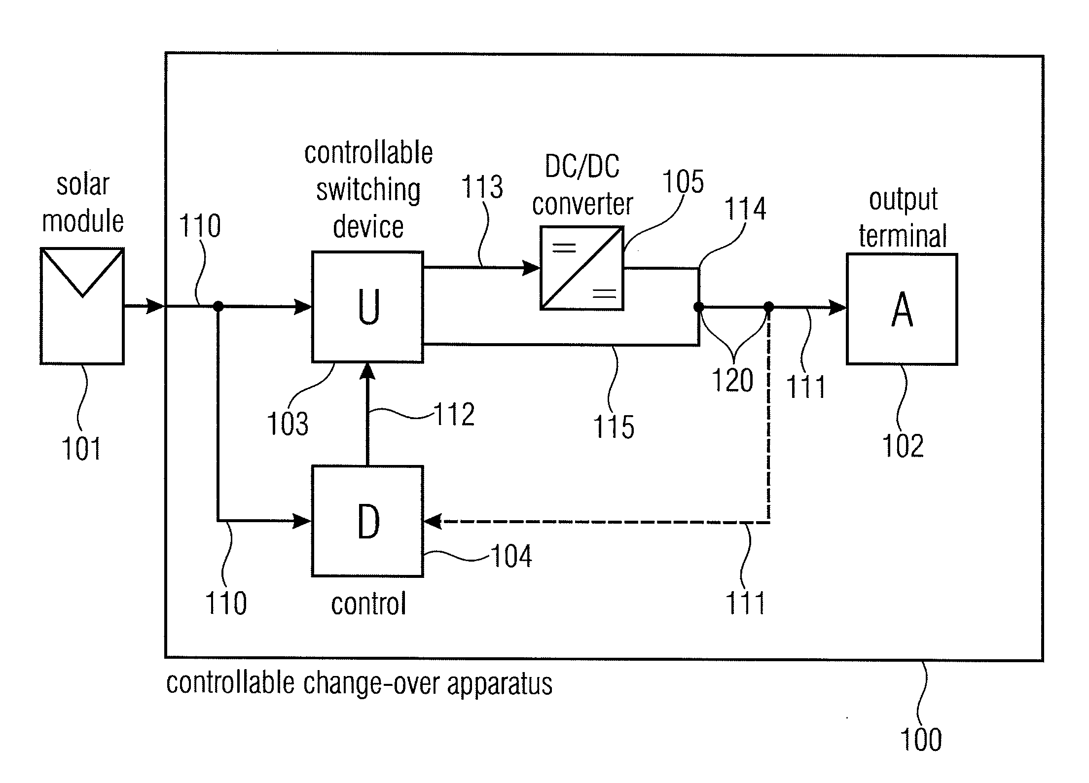
[0014]It is a basic idea of the present invention that power increase can be obtained when a change-over option is provided, according to which the solar module is connected directly to an output or module terminal, respectively, or connected to the module terminal via a DC / DC converter. Which of the two connection types is to be used for optimal energy usage can be determined by a control setting a controllable switching device to a first position, where the solar module is connected to the module terminal via the DC / DC converter, by using a performance characteristic present at the power output of the solar module or the module terminal, or to the second position, where the solar module is directly connected to the module terminal. In other words, the power characteristic at the power output of the solar modules including information about the currently generated power of the solar module can be used for causing efficient control of the controllable switching device with regard to increasing the efficiency of the solar module.

Problems solved by technology

Due to the fact that the bypass diode is conductive, the voltage of the shaded module string becomes almost zero (approximately −1 Volt), such that the shaded module string does no longer produce any power.
It is, however, a disadvantage that the DC / DC converter also operates in the non-shaded case and, produces electrical losses and reduces the overall efficiency of the solar generator.

Method used


Image

  • Controllable Change-Over Apparatus for a Solar Module
  • Controllable Change-Over Apparatus for a Solar Module
  • Controllable Change-Over Apparatus for a Solar Module

Examples


Embodiment Construction

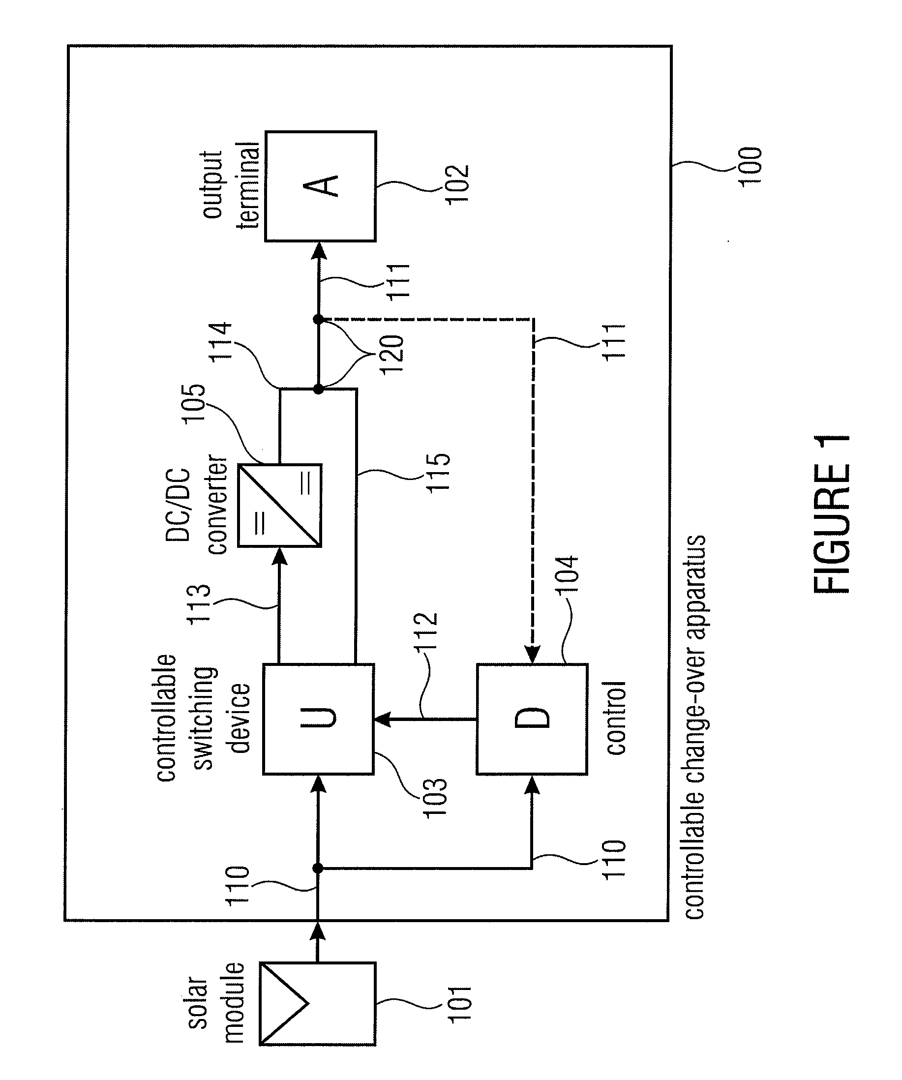
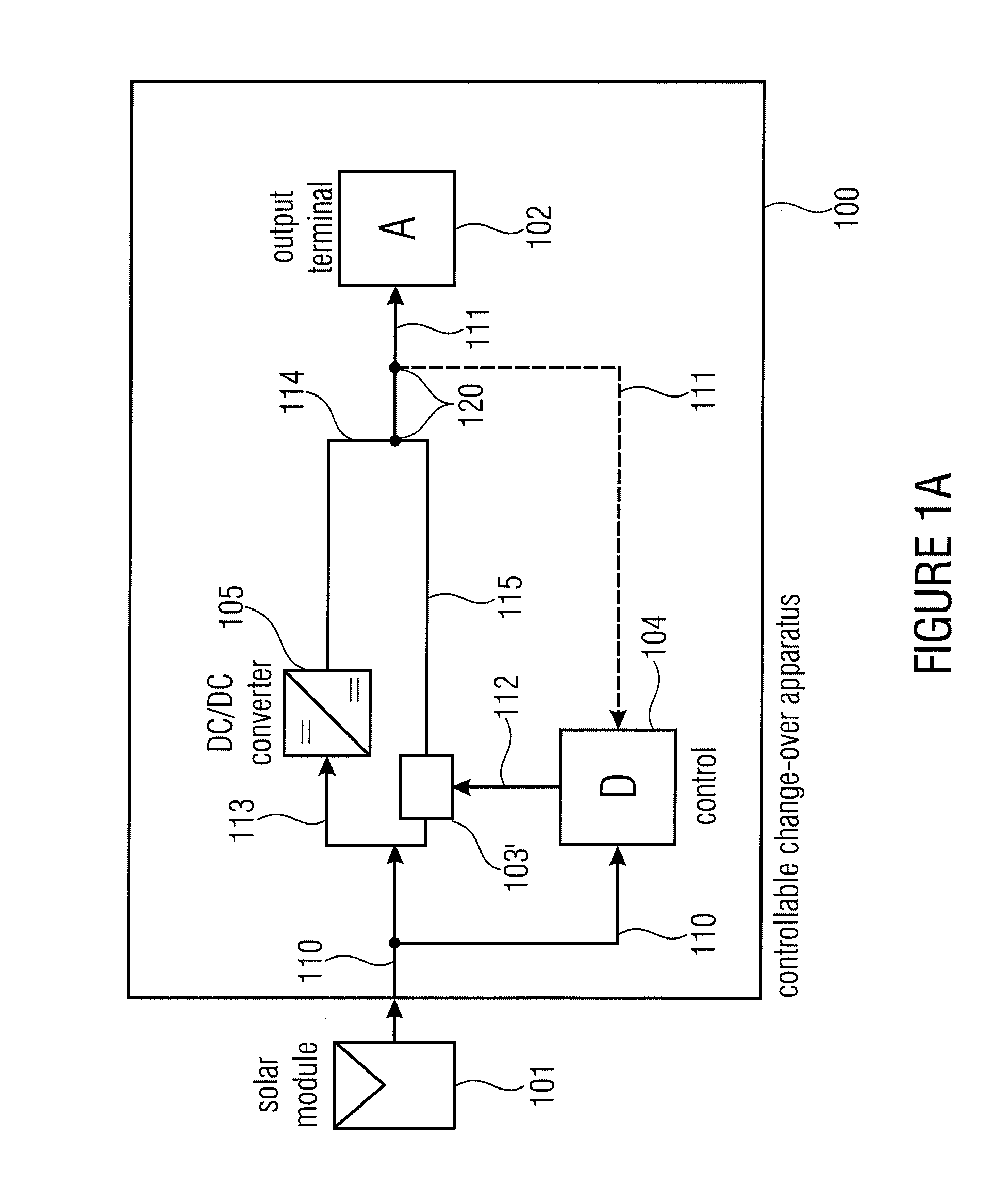
[0023]FIG. 1 shows a block diagram of a controllable change-over apparatus 100 for a solar module 101. The same comprises an output terminal 102, a controllable switching device 103, a control 104 as well as a DC / DC converter 105.

[0024]The solar module 101 comprises an output 110 connected to an input of the controllable switching device 103 and the control 104. The controllable switching device 103 has two outputs 113 and 115, the output 113 being connected to an output terminal 102 via the DC / DC converter 105, and the output 115 being connected directly to the output terminal 102. The control 104 has an input 110 connected to the output of the solar module and / or a second input 111 connected to the output terminal 102. In other words, in FIG. 1, a node 120 exists to which an output of the DC / DC converter 105 and the second output 115 of the controllable switching device 103 as well as the output terminal 102 and the second input of the control 104 are connected.

[0025]The controlla...


PUM


Abstract

Controllable change-over apparatus for a solar module comprises an output terminal, a DC / DC converter, a controllable switching device and a control. The controllable switching device is implemented with a first switch position and a second switch position, wherein, in the first switch position, a power output of the solar module is connected to the output terminal via the DC / DC converter, and, in the second switch position, the power output of the solar module is connected to the output terminal by bypassing the DC / DC converter. The control switches the controllable switching device by using a performance characteristic for switching the same to the first or second switch position. In particular, the control is implemented to connect the solar module directly to its output terminal in the case of high power dissipation of the same, i.e. at strong solar radiation, and to connect the solar module to the output terminal via the DC / DC converter in the case of weak power dissipation of the same, i.e. during shading, which significantly increases the efficiency compared to a fixed connection of the solar module.

Description

CROSS-REFERENCE TO RELATED APPLICATION[0001]This application is a U.S. National Phase entry of PCT / EP2008 / 007285 filed Sep. 5, 2008, and claims priority from German Patent Application No. 102007048974.0 filed Oct. 12, 2007, and German Patent Application No. 102008004675.2 filed Jan. 16, 2008, all of which are incorporated herein by references hereto.BACKGROUND OF THE INVENTION[0002]The present invention relates to a controllable change-over apparatus for a solar module and a method for controlling the same.[0003]A solar module converts electromagnetical radiation, such as sunlight, into electric energy and comprises, for example, several solar cells.[0004]Solar modules are connected individually or in groups, for example, in photovoltaic plants, small power-supply independent users, or for power supply of spacecrafts.[0005]The electric power ratings of a solar module characterizing a solar module are, for example, open-circuit voltage and short-circuit current. The same can depend o...

Claims


Application Information

Patent Timeline
Patent Type & Authority Applications(United States)
IPC IPC(8): H02H3/42
CPCG05F1/67H01L31/02021Y02E10/58H02J3/385H02J7/35H02J2300/10H02J2300/26H02J3/381Y02E10/56
Inventor BURGER, BRUNOSCHMIDT, HERIBERT
Owner FRAUNHOFER GESELLSCHAFT ZUR FOERDERUNG DER ANGEWANDTEN FORSCHUNG EV
Learn More