Two-piece heat sink stud

Inactive Publication Date: 2010-11-25
PEM MANAGEMENT INC
View PDF20 Cites 19 Cited by
  • Summary
  • Abstract
  • Description
  • Claims
  • Application Information

AI Technical Summary

Benefits of technology

[0006]In order to solve the problem in the art, the present fastening system has been devised. This fastening system utilizes a self-clinching stud assembly constructed by axially interfitting two flat sheet metal members. Each member has forked ends which when axially plugged together in criss-cross fashion create a unified fastener with side structures that can permanently clinch into a heat sink. After attachment to the heat sink, the stud presents two opposite attachment ends with tines which extend from the top and bottom of the heat sink. As finally assembled, a fan attaches to the t

Problems solved by technology

Computer processors and graphics generator electronics produce excessive waste heat.
If the springs are not sized properly, or if the circuit board material happens to be thinner than originally specified, damage to the PC board can occur since the spring force can cause bending of the board beneath the hea

Method used


Image

  • Two-piece heat sink stud
  • Two-piece heat sink stud
  • Two-piece heat sink stud

Examples


Example

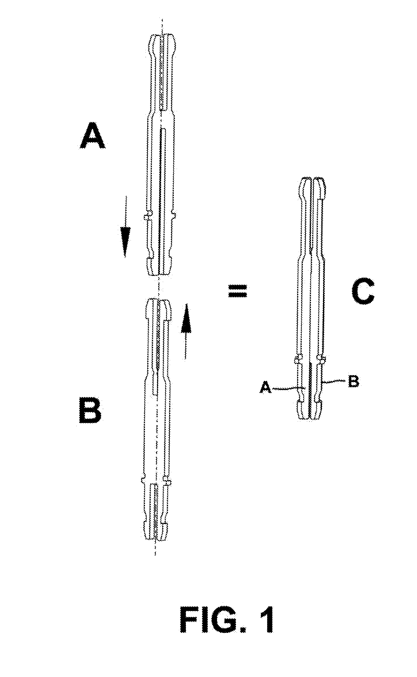
[0020]Referring now to FIG. 1, two interfitting parts A and B when axially plugged together comprise the assembled mounting stud C. The two parts are preferably, but not limited to, flat sheet metal stampings composed of a metal which is suitable for its intended purpose such as steel. In the completed stud C, the first member A and second member B are shown united with side edge features spaced 90 degrees apart. The individual parts are coextensive being flush at both opposite ends. The resultant mounting stud is sufficiently strong so that it can provide the force necessary to firmly join the fan heat sink, circuit board, and spring components as further described below. Because the stud may be manufactured from inexpensive stamped sheet metal, it is very economical to produce but it is not limited to this method of production. The parts could also be photo etched, laser cut, wire edm cut or water jet cut from flat blanks

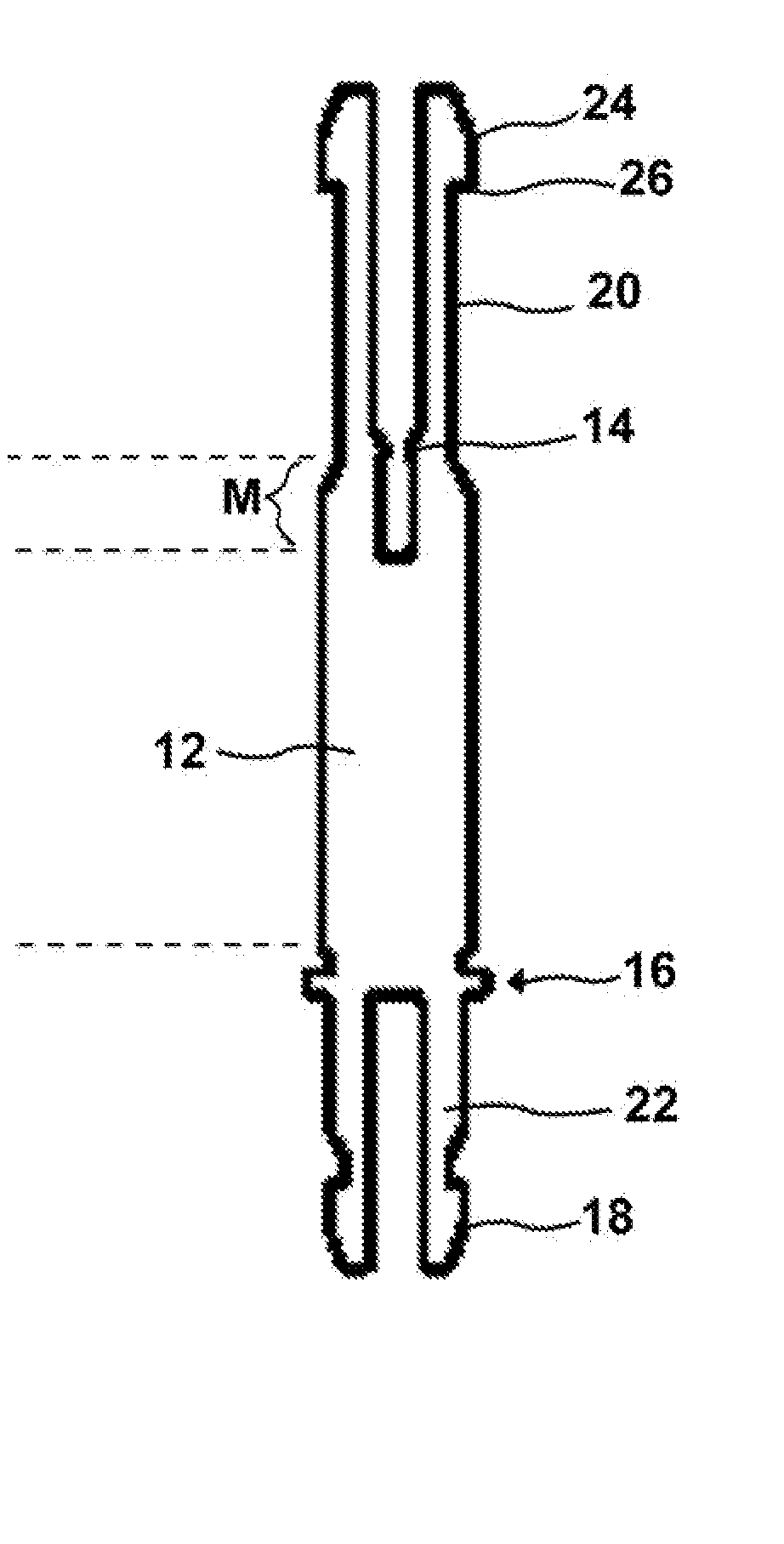
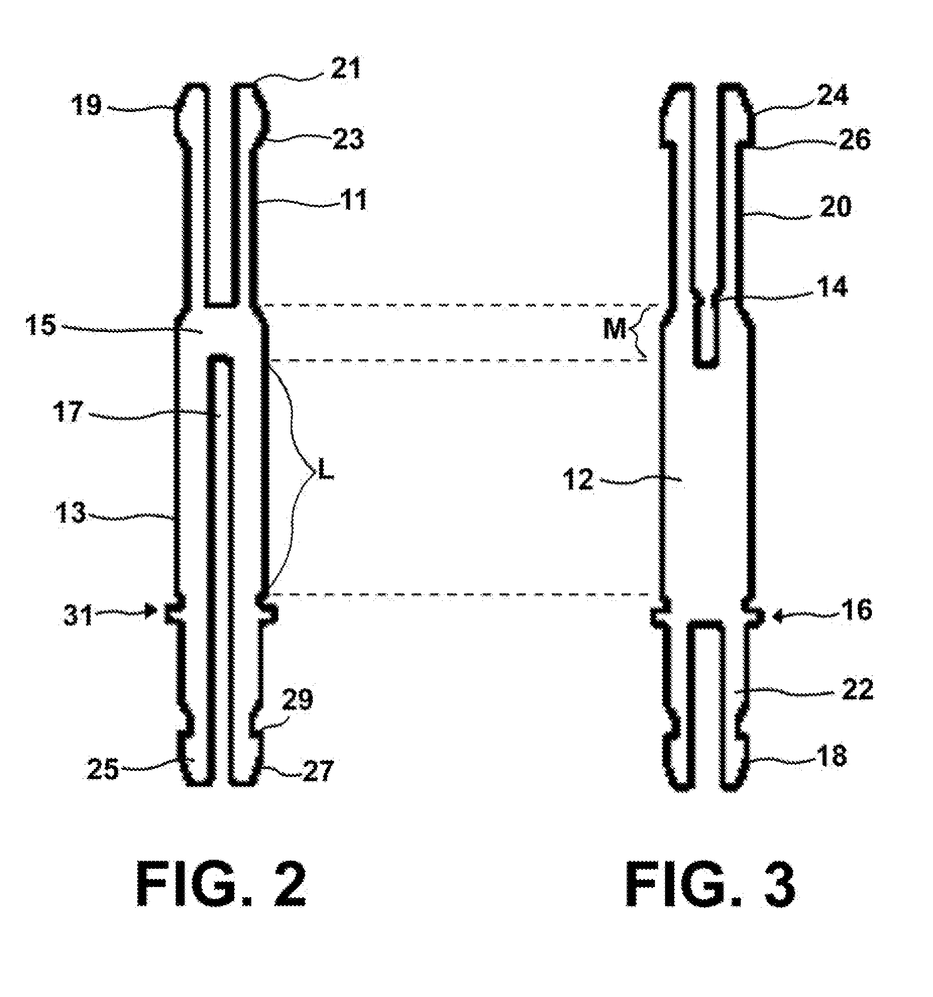
[0021]Referring now to FIGS. 2 and 3, the two interfitting h...


PUM


Abstract

A fastening system for a heat sink mounted on a circuit board utilizes a self-clinching stud assembly constructed by axially interfitting two flat sheet metal members. Each member has forked ends which when axially plugged together in criss-cross fashion create a unified fastener with side structures that can permanently clinch into a heat sink. After attachment to the heat sink, the stud presents two opposite attachment ends with tines which extend from the top and bottom of the heat sink. As finally assembled, a fan attaches to the top end of the studs above the heat sink while the opposite end of the stud which extends from the bottom of the heat sink passes through the circuit board to attach to a retaining leaf spring which presses against the back side of the board. Thus, all of the components are joined by a single stud.

Description

RELATED APPLICATION[0001]This patent application is related to provisional patent application Ser. No. 61 / 180,264 entitled “Two-Piece Heat Sink Stud” filed on May 21, 2009, priority from which is hereby claimed.FIELD OF THE INVENTION[0002]The present invention relates to an electronic assembly and more specifically to through-studs which attach electronic devices sandwiched together to a circuit board. More specifically, the invention relates to a fastening structure which simultaneously joins a cooling fan, a heat sink, a computer processor, a circuit board and a retaining spring clip.BACKGROUND OF THE INVENTION[0003]Computer processors and graphics generator electronics produce excessive waste heat. This heat must be removed from the processor chip to avoid damage to the chip. Extruded heat sinks and plastic fans are often employed to remove this excess heat and keep the processing chip cool. Some heat sink systems incorporate a fan that is fastened to the top of the heat sink to ...

Claims


Application Information

Patent Timeline
IPC IPC(8): H05K7/20
CPCH01L23/4093H01L2924/0002H01L2924/00
Inventor MALONEY, MICHAEL J.
Owner PEM MANAGEMENT INC
Why Eureka
Try Eureka