
Image processing method, image processing apparatus, and porgram

a technology of image processing and porgram, applied in image memory management, instruments, computing, etc., can solve the problems of image processing which cannot be dealt with, product cost, and most external memories having a limitation on memory, so as to reduce the capacity of delay memory

Inactive Publication Date: 2010-11-25
CANON KK
View PDF6 Cites 5 Cited by
  • Summary
  • Abstract
  • Description
  • Claims
  • Application Information

AI Technical Summary

Benefits of technology

[0025]The present invention provides an image processing method and apparatus capable of flexibly coping with even changes of the data resolution and the number of references in order to achieve image processes in various forms in a predetermined memory band while reducing the capacity of the delay memory, similar to the conventional technique.

Problems solved by technology

In the field of image processing methods and apparatuses, however, there are many image processes which cannot be dealt with by considering only local or neighbor image processing such as spatial filtering described in U.S. Pat. No. 6,587,158, Japanese Patent Laid-Open No. 2000-312327, Japanese Patent No. 3733826, and Japanese Patent Laid-Open No. 2006-139606.
Owing to a limitation on product cost, most external memories have a limitation on the memory band permissible when reading out a plurality of field images from the external memory.
However, the conventional technique does not examine a flexible change of the band area in accordance with the resolution and number of data for a plurality of correction data for one image data, a plurality of image data, and a plurality of successive field images.

Method used


Image

  • Image processing method, image processing apparatus, and porgram
  • Image processing method, image processing apparatus, and porgram
  • Image processing method, image processing apparatus, and porgram

Examples


first embodiment

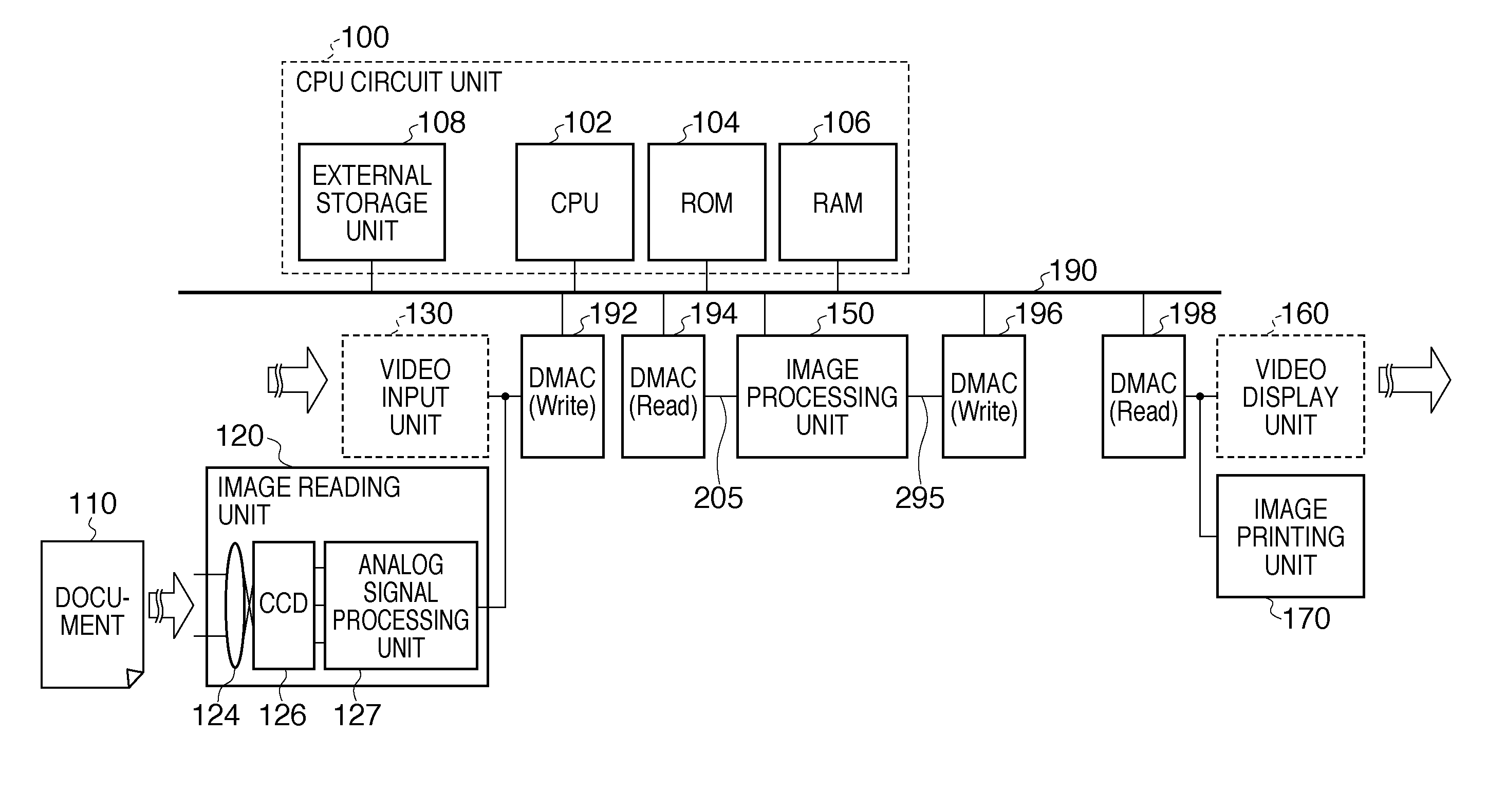
[0047]FIG. 1 is a block diagram exemplifying the overall arrangement of an image processing apparatus according to the

[0048]In FIG. 1, an image reading unit 120 includes a lens 124, CCD sensor 126, and analog signal processing unit 127. In the image reading unit 120, the CCD sensor 126 converts image information of a document 110, whose image is formed on the CCD sensor 126 via the lens 124, into R (Red), G (Green), and B (Blue) analog electrical signals. The analog signal processing unit 127 receives the analog electrical signals of the converted image information, performs correction and the like for each of R, G, and B, and converts them into digital signals (analog-to-digital (A / D) conversion). As a result, digital full-color signals (to be referred to as digital image data) are generated.

[0049]A DMAC (Direct Memory Access Controller) 192 whose operation is set in advance by a CPU 102 stores the generated digital image data in a RAM 106 of a CPU circuit unit 100 via a shared bus...

second embodiment

[0051]Finally, the CPU 102 sets a DMAC 198 to read out the digital image data which have undergone image processing and are stored in the RAM 106, and output them to an image printing unit (printer) 170. The image printing unit (printer) 170 includes, for example, a printout unit (not shown) such as a raster plotter using an inkjet head, thermal head, or the like. The image printing unit (printer) 170 prints an image on a sheet in accordance with an input digital image signal. Alternatively, a video display unit 160 such as a display displays and outputs an image in the second embodiment to be described later.

[0052]The CPU circuit unit 100 includes the arithmetic control CPU 102, a ROM 104 which stores permanent data and programs, the RAM 106 used to temporarily save data and load a program, and an external storage unit 108. The CPU circuit unit 100 controls the image reading unit 120, image processing unit 150, image printing unit (printer) 170, and the like to comprehensively cont...


PUM


Abstract

When processing image data by referring to at least one of reference image data and correction data, an image is processed in a unit of band area by dividing image data of a target image in a plurality of band areas. In this case, the minimum transfer unit of the image data is set. The minimum transfer unit of at least one of the reference image data and the correction data is obtained to process the image data in the minimum transfer unit. The transfer rate of the image data is determined so that the image data to be buffered fits in a capacity of a buffer available in image processing. The height of the band area to be created by division is determined based on the ratio of the transfer rate of the image data to the minimum transfer unit of the image data.

Description

BACKGROUND OF THE INVENTION[0001]1. Field of the Invention[0002]The present invention relates to an image processing method, image processing apparatus, and program. Particularly, the present invention is suitably applied when handling a plurality of image data, correction data, and the like in a main memory for image processing with dividing them, and sequentially reading out necessary data to perform image processing and correction processing.[0003]2. Description of the Related Art[0004]Conventionally, local or neighbor image processing such as spatial filtering is done when forming an image. Local image processing is image processing which executes any calculation using all pixels falling within a spatial filtering region including a pixel to be processed. In the following description, a pixel to be processed will be simply referred to as a pixel of interest.[0005]For example, spatial filtering such as edge enhancement processing or blur processing is performed for digital image ...

Claims


Application Information

Patent Timeline
IPC IPC(8): G06K9/34
CPCG06T1/60H04N1/409H04N1/4092
Inventor ITO, TADAYUKI
Owner CANON KK
Learn More