Fluid heating device

a heating device and flue gas technology, applied in the direction of service pipe systems, pipe heating/cooling, lighting and heating apparatus, etc., can solve the problems of continuous electric power loss, limited capacity that can be immediately used, and difficulty in reducing the size of storage-type hot water supply systems, etc., to prevent the exposure of ceramic heaters, rapid response, and uniform temperature

Inactive Publication Date: 2010-11-25
CM TECH CO LTD
View PDF3 Cites 21 Cited by
  • Summary
  • Abstract
  • Description
  • Claims
  • Application Information

AI Technical Summary

Benefits of technology

[0022]Although it is possible to slightly reduce the size and improve the response, but it is also limitative, in the instantaneous-heating type hot water supply system using a ceramic heater having high heating output in order to overcome the problems in the storage-typed hot water supply system. A structure that can improve thermal non-uniformity because the ceramic heater is vulnerable to a thermal shock is required; however, the cylindrical ceramic heater has problems, such as limitative heating response and thermal shock breakage due to development of bubbles, such that it is limitative to improve the heating output.
[0032]Therefore, it is possible to reduce the size without a hot water storing tank and prevents unnecessary loss of power, such that there are many advantages to reduce power consumption.

Problems solved by technology

It is difficult to reduce the size of the storage-typed hot water supply system of the related art and the capacity that can be immediately used is limited.
Electric power loss continuously occurs while the system is not used and the tank may be constantly exposed to insanitation state.
Although it is possible to slightly reduce the size and improve the response, but it is also limitative, in the instantaneous-heating type hot water supply system using a ceramic heater having high heating output in order to overcome the problems in the storage-typed hot water supply system.
A structure that can improve thermal non-uniformity because the ceramic heater is vulnerable to a thermal shock is required; however, the cylindrical ceramic heater has problems, such as limitative heating response and thermal shock breakage due to development of bubbles, such that it is limitative to improve the heating output.
In a flat plate ceramic heater that is another configuration of the instantaneous-heating type, thermal non-uniformity is increased by the structure that reduces the heating surface, increases a difference in temperature of one heating plate, and have a difficulty in removing the bubbles generated, such that a problem may occur in durability and safety of the ceramic heater.
Further, the improved structure of the flat plate ceramic heater does not reduce the heating surface because the walls forming the flow paths does not contact the heating surface; however, the response may decreases due to the structure that heats the hot water sub-tank with one heater.

Method used


Image

  • Fluid heating device
  • Fluid heating device
  • Fluid heating device

Examples


embodiment 1

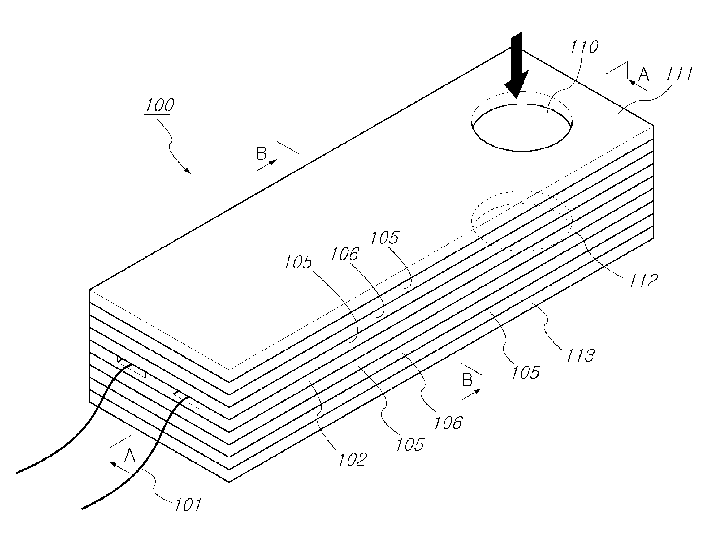
[0088]A fluid heating device was configured such that a heating area was 7.5 cm2[=50×15], two plate ceramic heaters having heating resistance of 35Ω were connected in parallel, and the cross-sectional areas of horizontal and vertical flow paths were 0.32 cm2[=2 mm(h)×16 mm (w, heating surface), w / h=8].

[0089]When a voltage of 220V was applied and water continuously flowed at a flow rate of 1˜1.2 L per minute, the water having initial temperature of 25° C. was continuously heated by 50˜55° C. and power of 2.2 kW was consumed. This heating experiment was continued for about 5000 hours (210 days×24 hr), but the inner ceramic heater was not broken.

embodiment 2

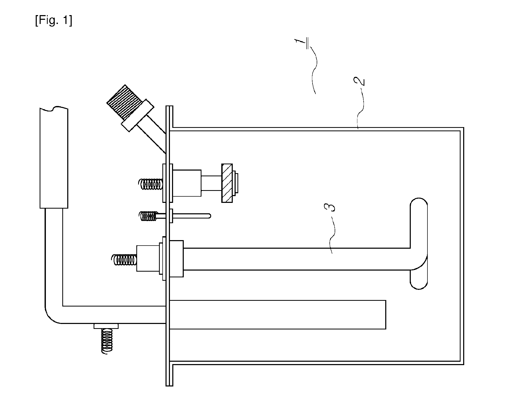
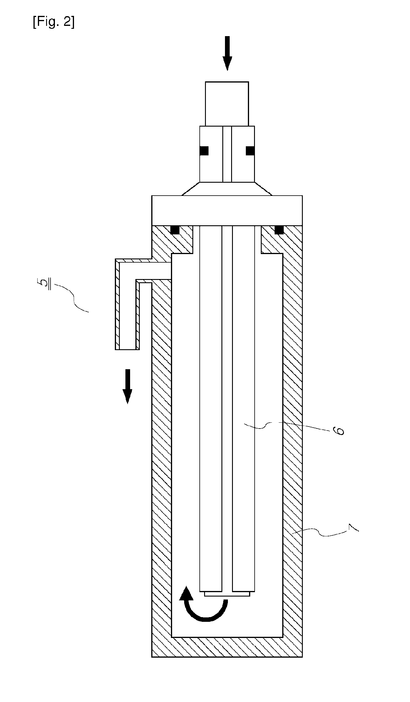
[0090]A fluid heating device is configured, in which a cylindrical ceramic heater having heating resistance of 20Ω, an inner diameter of 6.5 mm, an outer diameter of 10 mm, a heating length of 80 mm was used and a flow path forming plate (5 mm outer diameter and 4 mm inner diameter) was inserted inside the inner circumference.

[0091]The inner diameter of a case was set to 12 mm such that the aspect ratio of the flow path in the inner circumference was 24 and the aspect ratio of the outer circumference was 34.5, in this device. A voltage of 220V was applied and water flowed at a flow rate of 1˜1.2 L per minute.

[0092]The water having initial temperature of 25° C. was continuously heated by 45˜50° C. and this heating experiment was continued for about 3000 hours (125 days×24 hr), but the inner ceramic heater was not broken.

embodiment 3

[0093]A fluid heating device was configured such that a heating area was 7.5 cm2[=50×15], four plate ceramic heaters having heating resistance of 40Ω were connected in series, and the cross-sectional areas of horizontal and vertical flow paths were 0.08 cm2[=0.5 mm(h)×16 mm (w, heating surface), w / h=32].

[0094]Vapor at 120˜200° C. was produced at the outlet hole by power of 150˜250W by injecting mist (about 1 g water / L, air containing micro-drops of water produced by ultrasonic vibration) at 10 LPM and applying a voltage of 220V to the terminal of the series of ceramic heaters.


PUM

PropertyMeasurementUnit
temperatureaaaaaaaaaa
aspect ratioaaaaaaaaaa
lengthaaaaaaaaaa

Abstract

The present invention relates to a fluid heating device which can instantaneously heat a fluid which is flowing for the purpose of supply or circulation. It comprises: a ceramic heater in the form of a flat plate having terminal lead wires for applying a power source; partition plates, to top and bottom of the ceramic heater, which allow the fluid which is to be heated to move towards the ceramic heater and which said partition plates have horizontal-movement fluid pathways such that fluid which has been heated by means of the ceramic heater is discharged; a flow path forming plate having a fluid through path such that the fluid on the horizontal-movement fluid pathways can move vertically to the fluid pathway of the next layer; an upper cover having an inlet hole for the supply of a fluid for heating the outside surface of the uppermost partition plate; and a final lower cover having an outlet hole for discharging the heated fluid onto the outside surface of the lowermost partition plate.

Description

BACKGROUND OF THE INVENTION[0001]1. Field of the Invention[0002]The present invention relates to a fluid heating device, in more detail, a small-sized fluid heating device that can instantaneously heat fluid flowing for supply or circulation, due to high heating efficiency.[0003]2. Description of the Related Art[0004]A typical fluid heating device 1 is shown in FIG. 1, which is a storage-typed hot water supply system that heats a predetermined amount of water stored in a tank 2 and retains the heat always at predetermined temperature (e.g., about 40° C.)[0005]Because the storage amount is limited in the storage-typed hot water supply system, hot water at predetermined temperature is supplied while the storage amount of water is discharged; however, the hot water gradually decreases in temperature and hot water under the predetermined temperature is discharged, when the system is used for a long time above the storage amount of water, such that it has a limit as a hot water supply sy...

Claims


Application Information

Patent Timeline
Patent Type & Authority Applications(United States)
IPC IPC(8): F16L53/00
CPCF24H1/121F24H1/202H05B2203/021H05B3/42F24H9/1827F24H1/18F24H1/20
Inventor MIN, HUNG SIKAN, YOUNG GEUNYANG, SUNG JIN
Owner CM TECH CO LTD
Why Eureka
Try Eureka