
Cell Connector

Inactive Publication Date: 2010-11-25
CHENG UEI PRECISION IND CO LTD
View PDF3 Cites 7 Cited by
  • Summary
  • Abstract
  • Description
  • Claims
  • Application Information

AI Technical Summary

Benefits of technology

[0005]An object of the present invention is to provide a cell connector adapted for electrically connecting at least one cell. The cell connector includes a plate-shaped connecting member made of metal material with high conductivity, and at least one welding member mounted on the connecting member for being welded with the cell. The welding member is made of weldable metal solder. The connecting member has a lower resistivity than the welding member. Therefore, the cell connector of the present invention not only is easily welded, but also can reduce the energy loss thereon, and moreover, the cost is also advantageously reduced.

Problems solved by technology

However, the nickel material has a high resistivity that results in a great energy loss on the cell connector.
However, that results in an increase of the cost and an inconvenient welding between the cell connector and the cell.

Method used


Image

  • Cell Connector
  • Cell Connector
  • Cell Connector

Examples


Embodiment Construction

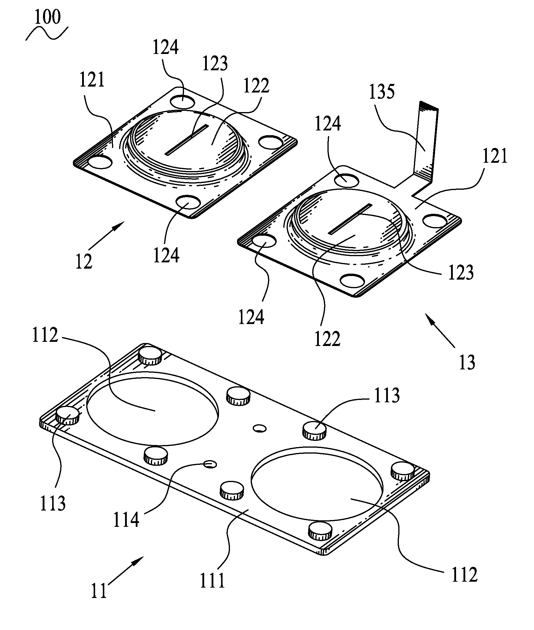
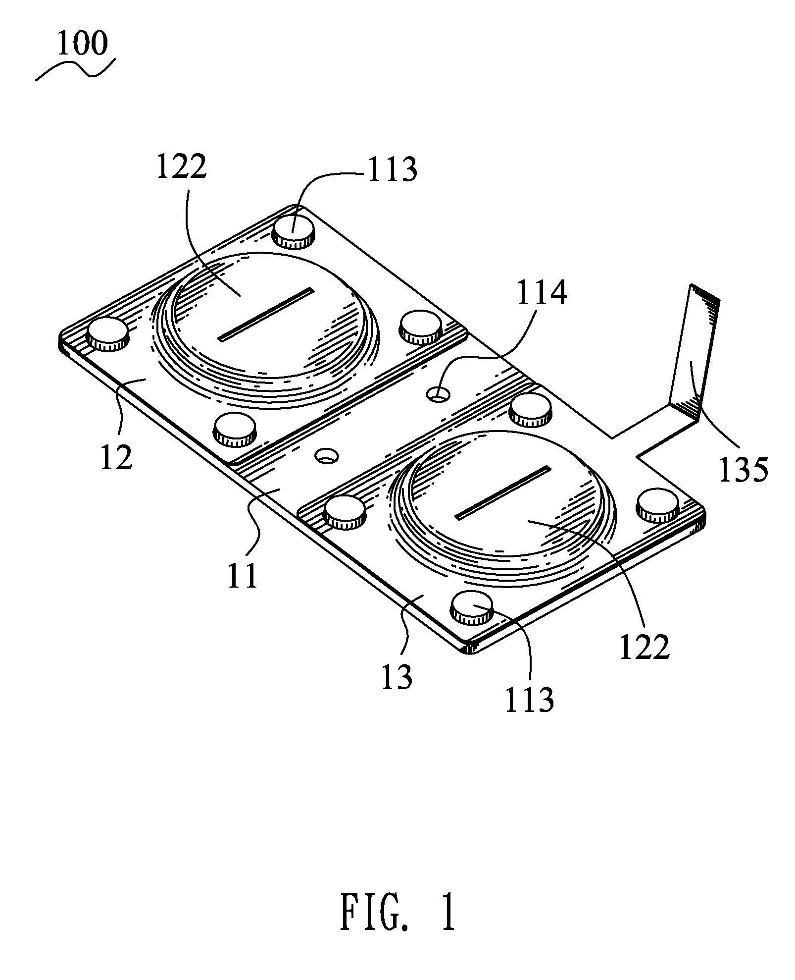
[0012]Referring to FIG. 1 and FIG. 2, a cell connector 100 according to a first embodiment of the present invention includes a connecting member 11, a first welding member 12 and a second welding member 13.

[0013]Referring to FIG. 2 again, the connecting member 11 is made by means of punching a copper plate with high conductivity and has a flat rectangular base board 111. Two ends of the base board 111 respectively define a round welding opening 112 penetrating therethrough. The two ends of the base board 111 are further punched upward to respectively form a plurality of cylindrical fixing lumps 113 located orderly around the corresponding welding opening 112. A middle of the base board 111 defines two fixing holes 114 located between the two welding openings 112.

[0014]In FIG. 2, the first welding member 12 and the second welding member 13 are respectively made by means of punching a nickel plate with a good welding performance. The first welding member 12 has a flat square base plat...


PUM


Abstract

A cell connector adapted for electrically connecting at least one cell includes a plate-shaped connecting member made of metal material with high conductivity, and at least one welding member mounted on the connecting member for being welded with the cell. The welding member is made of weldable metal solder. The connecting member has a lower resistivity than the welding member. Therefore, the cell connector of the present invention not only is easily welded, but also can reduce the energy loss thereon, and moreover, the cost is also advantageously reduced.

Description

BACKGROUND OF THE INVENTION[0001]1. Field of the Invention[0002]The present invention relates to an electrical connector, and more particularly to a cell connector.[0003]2. The Related Art[0004]With the development of electronic technology, cells have been popularly used in our daily life for facilitating the using of electronic products. In order to meet power demands of the electronic products, a battery module is formed by series-parallel connection of a plurality of cells to supply power for the electronic products, wherein an electrical connection between the corresponding two cells is achieved by means of a cell connector. Traditionally, the cell connector is made by means of punching a nickel plate and is of strip shape. Two ends of the cell connector are respectively welded to a positive electrode of one cell and a negative electrode of the other cell so as to form the electrical connection between the two cells. However, the nickel material has a high resistivity that resul...

Claims


Application Information

Patent Timeline
IPC IPC(8): H01M2/26H01M50/503H01M50/516H01M50/522H01M50/529H01M50/541
CPCH01M2/204H01M2/105Y02E60/10H01M50/213H01M50/522H01M50/516H01M50/503
Inventor LAI, SHIH-POCHENG, SHENG-HAOYANG, TA-CHANGHUANG, PO-LAUNG
Owner CHENG UEI PRECISION IND CO LTD
Features
  • Generate Ideas
  • Intellectual Property
  • Life Sciences
  • Materials
  • Tech Scout
  • Unparalleled Data Quality
  • Higher Quality Content
  • 60% Fewer Hallucinations
Learn More