
Surgical tweezers

a technology of tweezers and tweezers, which is applied in the field of surgical tweezers, can solve problems such as the distortion of tweezers

Active Publication Date: 2010-11-25
MORIA
View PDF5 Cites 13 Cited by
  • Summary
  • Abstract
  • Description
  • Claims
  • Application Information

AI Technical Summary

Benefits of technology

[0015]The two handle elements of the tweezers are of a length shorter than the total length of the working part. Each is then fitted on the corresponding branch by engaging the branch in the groove and by fastening by any means appropriate for the materials constituting the working part and the handle (laser welding if they are both made of metal, adhesive, snap-fastening, . . . ). Under such circumstances, the working part possesses a root portion of the branches that extends well beyond the rear ends (proximal ends) of the handle elements so as to assist in handling of the tweezers by the operator.
[0020]This provision makes it possible to obtain excellent engagement between the points or the hooks of the tweezers, in spite of the dimensional uncertainties of parts made of plastics material.
[0021]Finally, in order to control interaction between the working part and the plastics handle, i.e. to ensure that the forces on each of them serve to ensure that the handle elements are held properly on the working part with stresses in balance so that no distortions are generated that might spoil the coincidence qualities, or lead to deterioration in coincidence qualities over time as a result of successive sterilizations, one of the flanks of each groove is provided with at least one portion in relief that is suitable for being deformed plastically by inserting the working part in the groove.

Problems solved by technology

It has been found that distortion of the tweezers is due to the direction of the force applied thereto by the surgeon's fingers.

Method used


Image

  • Surgical tweezers
  • Surgical tweezers
  • Surgical tweezers

Examples


Embodiment Construction

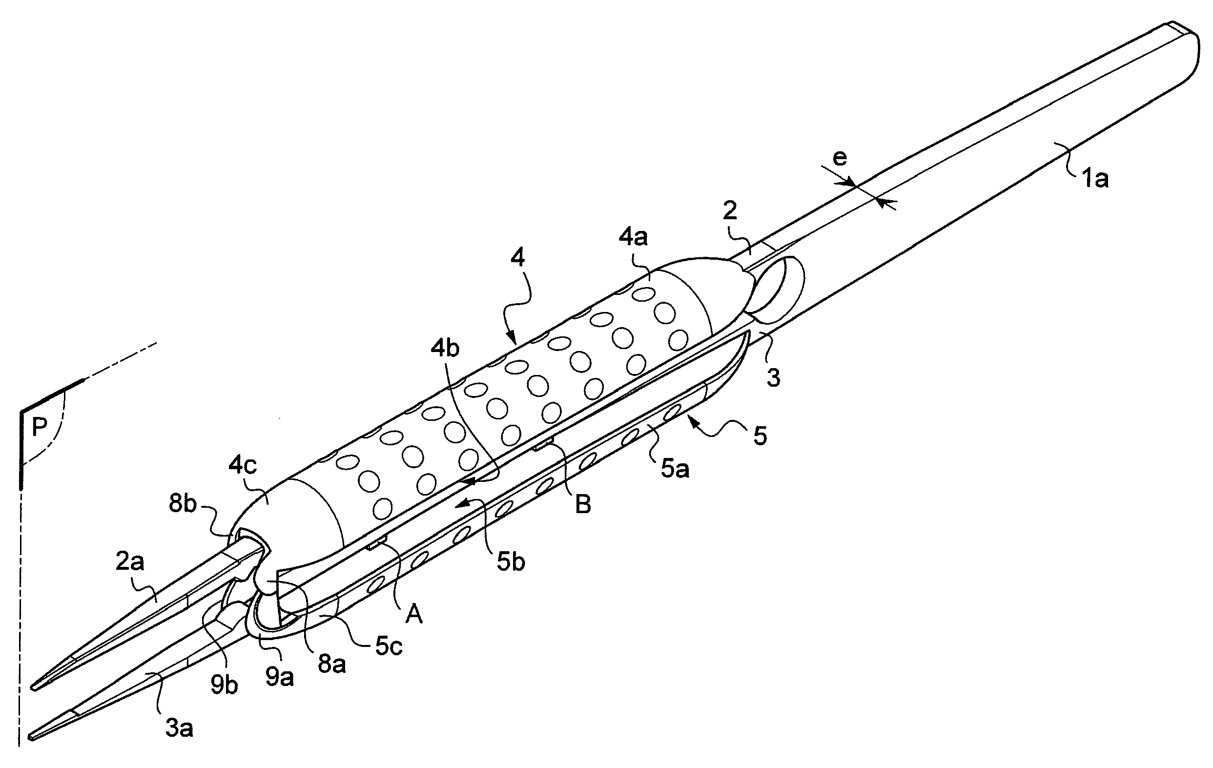
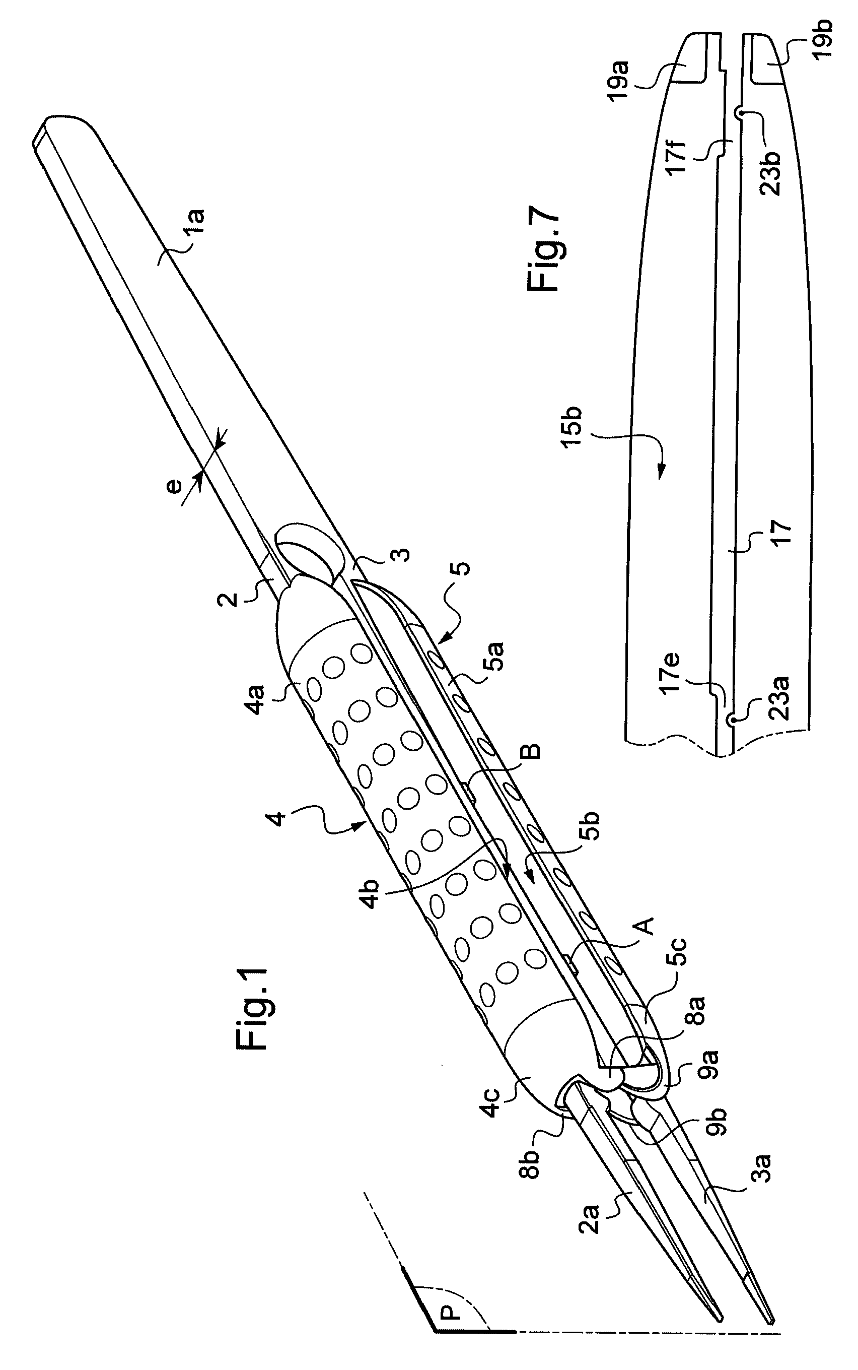
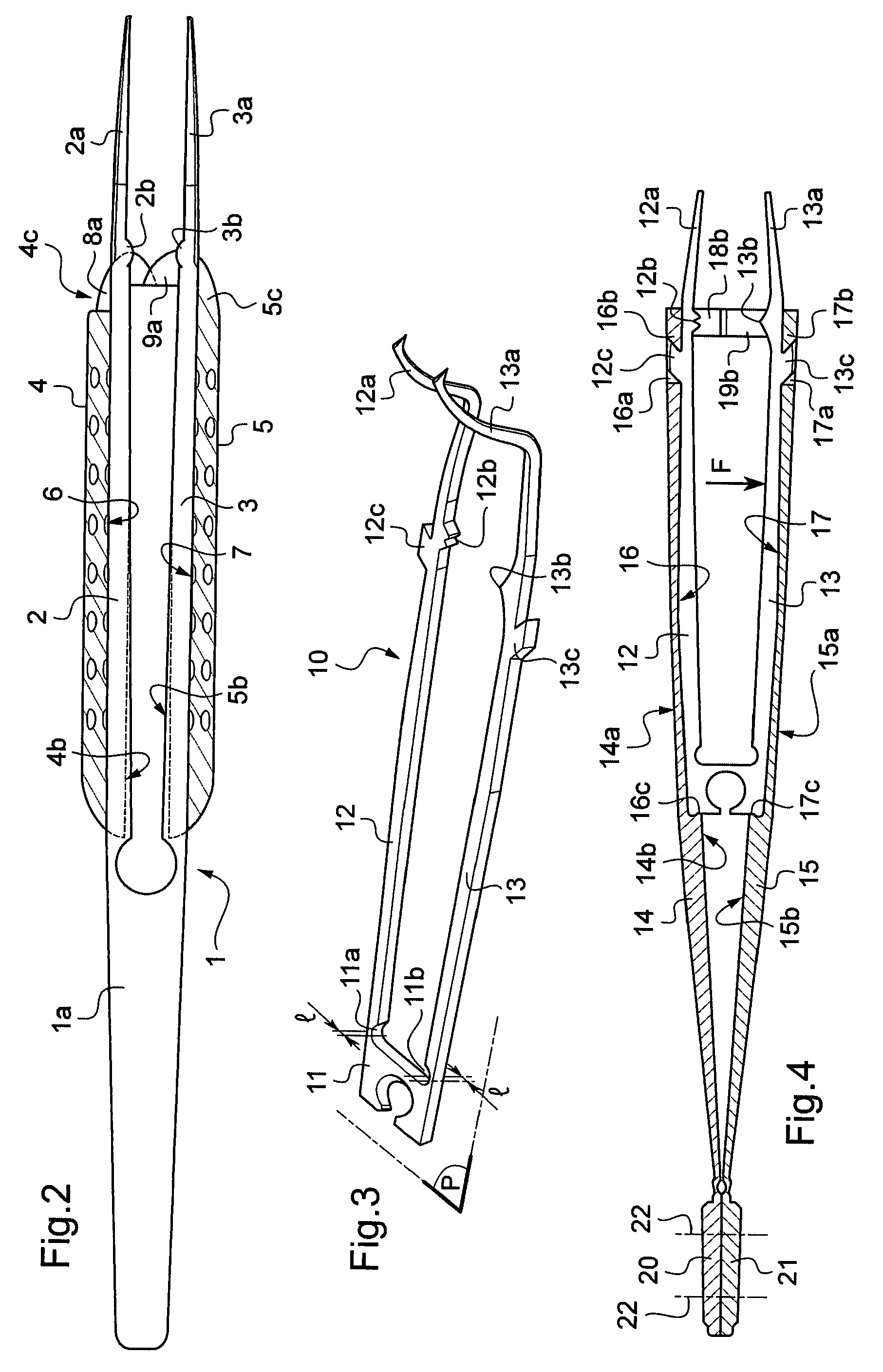
[0030]FIGS. 1 and 2 show tweezers for opthalmological surgery that comprise a one-piece working part 1 that is U-shaped, being obtained by cutting a metal sheet with a wire (electroerosion) or by any other technique such as precision electrochemical machining (PECM). This part 1 thus has two branches 2 and 3, with the free ends 2a and 3a of each of the branches being shaped into a point, in particular by machining. The thickness e of the metal sheet (or more generally of a flat blank that might be a plate of synthetic material, either of the type comprising a polymer matrix filled with a reinforcing material, or of the composite type, or obtained by the metal injection molding (MIM) fabrication method) is constituted by the dimension perpendicular to the plane P in which the branches move.

[0031]The tweezers also have elements 4 and 5 for manipulating the working part 1, together forming a handle for gripping the tweezers.

[0032]Each element 4, 5 is in the form of an elongate body pre...


PUM


Abstract

The invention provides tweezers for microsurgery, in particular opthalmological surgery, the tweezers comprising a one-piece working part (1) of U-shape, with the free ends (2a, 3a) of each branch (2, 3) being shaped into a point, the part being derived from a flat blank of thickness (e) constituting the dimension perpendicular to the plane (P) in which the branches (2, 3) move, and elements for manipulating the working part together forming a handle for gripping the tweezers, wherein each element is in the form of an elongate body (4, 5) presenting a convex outside surface (4a, 5a) and a substantially plane surface (4b, 5b) having a longitudinal groove (6, 7) hollowed out therein to house one of the branches (2, 3) of the working part (1), the end of each handle element facing towards the points being provided with centering means (8a, 8b, 9a, 9b) co-operating with a complementary centering member of the corresponding end of the other element.

Description

[0001]The present invention relates to surgical tweezers, and more particularly to surgical tweezers for opthalmological surgery.BACKGROUND OF THE INVENTION[0002]Surgery of the eye requires instruments that are small and fine to act through openings of small size and on organs or tissue that are likewise of small size.[0003]Certain tweezers of this type are made from two metal blades that are hinged together in their middle portions or close to their active ends. The precision of the active ends of tweezers of this type depends on the care with which they are fabricated, and in particular on the slack that exists in the hinge. Furthermore, in use, this slack increases and precision decreases.[0004]There also exist tweezers that are made from flat blades that are curved perpendicularly to their thickness and that are united at their ends remote from their active ends. The stiffness of the arms formed by the blades is generally not satisfactory, and the practitioner does not have suff...

Claims


Application Information

Patent Timeline
IPC IPC(8): A61B17/50
CPCA61F9/007A61B17/30
Inventor AUFAURE, JEAN-LUCSEMPE, ANTOINE
Owner MORIA
Learn More