
Acceleration sensor

Active Publication Date: 2010-12-02
ROBERT BOSCH GMBH
View PDF6 Cites 15 Cited by
  • Summary
  • Abstract
  • Description
  • Claims
  • Application Information

AI Technical Summary

Benefits of technology

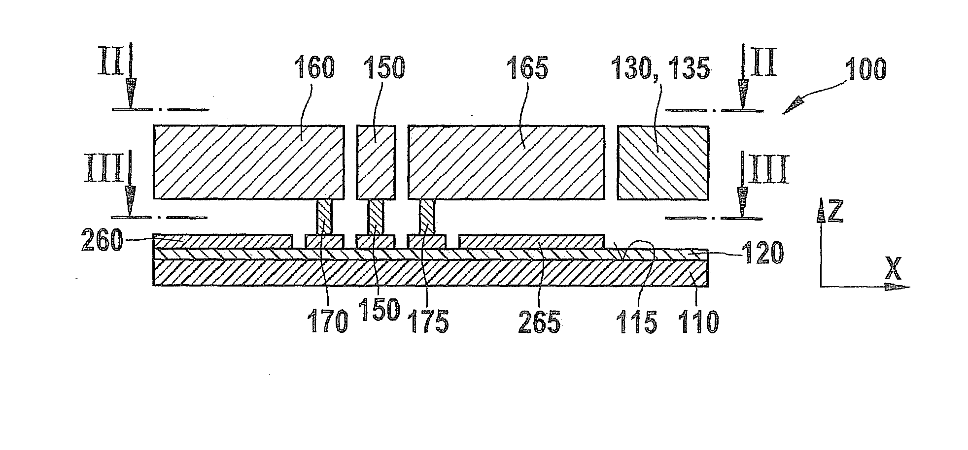
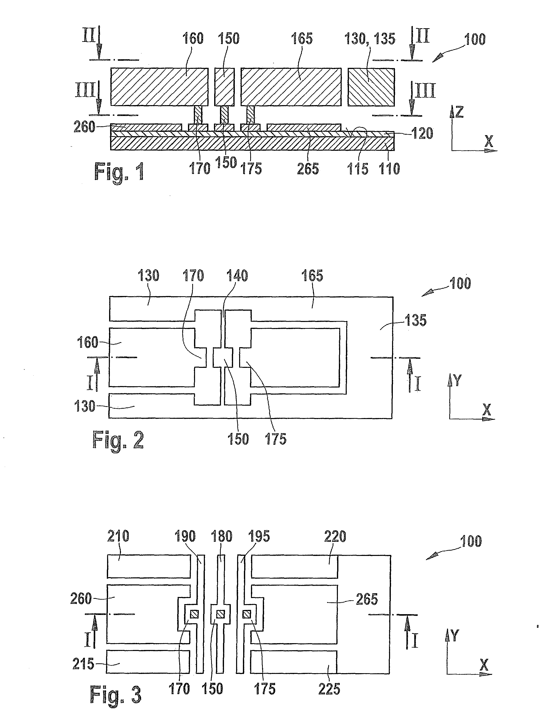
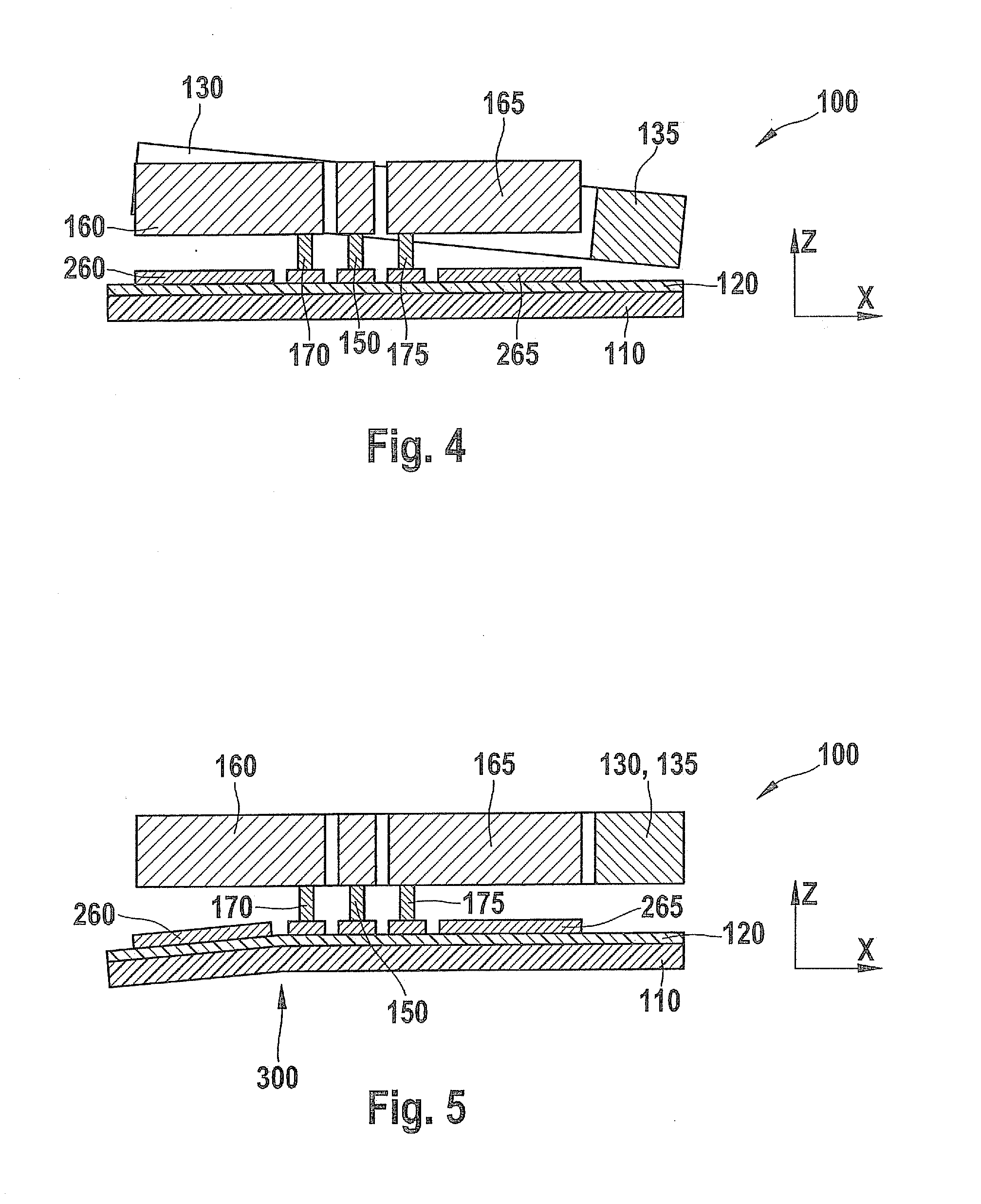
[0007]Advantageously, the first and second compensation electrodes do not as a first approximation react to an acceleration acting on the acceleration sensor. The first and second compensation electrodes react, however, to an asymmetrical bending of the substrate in a similar manner to the rocking mass. In that manner it is possible to distinguish the effects of an asymmetrical bending of the substrate from an acceleration and compensate for it. That advantageously permits the production of acceleration sensors that are markedly less sensitive to stress effects caused by a housing. That makes it possible to use types of housing that exert higher stress effects on the acceleration sensor but which in return are cheaper. For example, molded housings may be used instead of premolded housings.
[0009]The first counter-electrode may be electrically connected to the second compensation counter-electrode and the second counter-electrode is electrically connected to the first compensation counter-electrode. Such a complementary interconnection advantageously brings about automatic compensation for signal offsets caused by asymmetrical bending of the substrate.
[0011]It is also advantageous for the first compensation counter-electrode and the second compensation counter-electrode to be configured symmetrically to each other in terms of a mirroring at the torsion spring. Advantageously, that too assists in providing a capacity to compensate well for the effects of asymmetrical bending of the substrate.
[0012]In accordance with a development of the micromechanical acceleration sensor, without an acceleration acting on the acceleration sensor a first electrical sensor capacitance between the rocking mass and the first counter-electrode is of approximately the same magnitude as a first electrical compensation capacitance between the second compensation electrode and the second compensation counter-electrode, and a second electrical sensor capacitance between the rocking mass and the second counter-electrode is of approximately the same magnitude as a second electrical compensation capacitance between the first compensation electrode and the first compensation counter-electrode. Advantageously, that too assists in providing a capacity to compensate well for the effects of an asymmetrical bending of the substrate.
[0017]A plurality of first counter-electrodes and / or a plurality of first compensation counter-electrodes may also be provided. It is then advantageously possible to compensate for asymmetrical bending of the substrate acting in all directions of the plane of the substrate surface.
[0018]A method according to the present invention for operating a micromechanical acceleration sensor has method steps for acquiring a first sum of the first electrical sensor capacitance and the first electrical compensation capacitance, for acquiring a second sum of the second electrical sensor capacitance and the second electrical compensation capacitance, for calculating a difference between the first sum and the second sum, and for determining a magnitude and a direction of an acceleration acting on the acceleration sensor on the basis of the amount and sign of the difference. This method advantageously allows the effects of an asymmetrical bending of the substrate on the acceleration sensor to be differentiated from an acceleration acting on the acceleration sensor.

Problems solved by technology

A disadvantage of such acceleration sensors is their sensitivity toward interference caused by mechanical stress.

Method used


Image

  • Acceleration sensor
  • Acceleration sensor
  • Acceleration sensor

Examples


second embodiment

[0046]FIG. 6 shows a plan view of an acceleration sensor 1100 in accordance with a FIG. 7 shows, in a section parallel to the x-y plane, the electrodes of acceleration sensor 1100 which are connected to substrate 110. Acceleration sensor 1100 has, connected to substrate 110, a third compensation counter-electrode 1260, a fourth compensation counter-electrode 1263, a fifth compensation counter-electrode 1266, a sixth compensation counter-electrode 1270, a seventh compensation counter-electrode 1273 and an eighth compensation counter-electrode 1276. In addition, acceleration sensor 1100 has, fixedly connected to the substrate, a third counter-electrode 1210 and a fourth counter-electrode 1220. Third counter-electrode 1210 is configured like a comb with four parallel teeth. Third, fourth and fifth compensation counter-electrode 1260, 1263 and 1266 are arranged in succession in y direction between the parallel teeth of third counter-electrode 1210. Fourth counter-electrode 1220 is conf...

third embodiment

[0049]FIGS. 8 and 9 show an acceleration sensor 2100 in accordance with a FIG. 9 shows, in a section parallel to the x-y plane, the counter-electrodes of acceleration sensor 2100 which are fixedly connected to the substrate. FIG. 8 shows, in a plan view, compensation electrodes 160, 165 arranged in z direction above compensation counter-electrodes 260, 265, and rocker 130 arranged in z direction above counter-electrodes 210, 215, 220, 225. In contrast to the embodiment of FIGS. 1 to 3, acceleration sensor 2100 has only one supply line 2180 and one suspension post 2150. Suspension post 2150 connects both first compensation electrode 160 and second compensation electrode 165 to supply line 2180. In addition, suspension post 2150 connects rocker 130 to supply line 2180 via torsion spring 140. Acceleration sensor 2100 thereby only permits compensation electrodes 160, 165 and rocker 130 to be kept to a common potential. In many applications, however, that does not represent any limitati...


PUM


Abstract

A micromechanical acceleration sensor includes a substrate with a substrate surface arranged in one plane, a first counter-electrode arranged on the substrate surface, a second counter-electrode arranged on the substrate surface, and a rocking mass arranged above the first counter-electrode and the second counter-electrode. The rocking mass is in this case connected to the substrate via a torsion spring which permits tilting of the rocking mass about an axis of rotation. Further provided are a first compensation counter-electrode arranged on the substrate surface and a second compensation counter-electrode arranged on the substrate surface. In addition, a first compensation electrode is arranged above the first compensation counter-electrode and a second compensation electrode is arranged above the second compensation counter-electrode.

Description

RELATED APPLICATION INFORMATION[0001]The present application claims priority to and the benefit of German patent application no. 10 2009 026 462.0, which was filed in Germany on Mar. 26, 2009, the disclosure of which is incorporated herein by reference.FIELD OF THE INVENTION[0002]The present invention relates to a micromechanical acceleration sensor and to a method for operating a micromechanical acceleration sensor.BACKGROUND INFORMATION[0003]Micromechanical acceleration sensors made from semiconductor substrates are known. It is further known to use, in the case of capacitive acceleration sensors having a detection direction perpendicular to a wafer plane, rocking electrodes which are based on a spring-mass system in which a movable seismic mass forms a plate capacitor with each of two counter-electrodes fixed to a substrate. The seismic rocking mass is in that case connected to the substrate via a torsion spring. If the mass of the seismic rocking electrode is distributed asymmet...

Claims


Application Information

Patent Timeline
IPC IPC(8): G01P15/125
CPCG01P15/125G01P2015/0831
Inventor REINMUTH, JOCHEN
Owner ROBERT BOSCH GMBH
Learn More