Device for Movement Between an Input Member and an Output Member

a technology of input member and output member, which is applied in the direction of manipulators, controlling members, instruments, etc., can solve the problems of mechanical eigen-frequencies (related to the ratio), highinertia (or mass), and low stiffness and strength, etc., to achieve excellent accessibility, large angular motion range, and improve device based

Active Publication Date: 2010-12-02
FORCE DIMENSION S A R L
View PDF17 Cites 73 Cited by
  • Summary
  • Abstract
  • Description
  • Claims
  • Application Information

AI Technical Summary

Benefits of technology

[0017]In order to improve devices based on parallel and hybrid kinematics structures on these aspects, a novel mechanism is disclosed for relative movement of an output member with respect to an input member providing at least two DOF of rotational type around remote rotation axes (i.e. remotely located at a given offset distance with respect to output member). Incorporating the present invention leads to structures with the advantage of allowing, for example, excellent accessibility around its remote rotation axes, large angular motion ranges, high stiffness (e.g. in designs with three bars since no bending and no torsion stresses occur in these bars, only tensile and compressive forces), low inertia and direct access to drive the at least two rotational DOF. Under specific geometrical conditions, the at least two remote rotation axes are intersecting in a common RRC and furthermore the remote rotation axes do not shift during rotational motion.
[0018]It is noted that incorporating the present invention in existing kinematics structures by substitution is the key to a whole new family of parallel and hybrid structures with improved performance (embodiments of such arrangements are, for example, defined in the claims).

Problems solved by technology

This serial arrangement of links and active joints offers large motion ranges, but inertia (or mass) is high (since actuators are carried by the structure) and stiffness and strength are low (since the complete forces and torques are transmitted through every link and joint of the kinematics chain, adding their compliances and weights).
The resulting mechanical eigen-frequencies (related to the ratio between stiffness and inertia) and motion dynamics are low; undesired bending and vibrations lead to low precision.
Drawbacks are reduced motion ranges (since the resulting workspace is defined by the intersection of several chains, which can furthermore interfere with each other and let undesired singular or unstable postures arise within the workspace), reduced accessibility to the end effector, greater volume occupied by moving mechanical parts and greater complexity due to the additional passive joints.
Known parallel and hybrid kinematics structures usually have their natural RC located somewhere in the inner side of the volume occupied by its moving mechanical parts with little or no accessibility to it, and have inherently low angular motion ranges due to mechanical interference issues and generally have undesired singular postures within the workspace.
However, this arrangement does not completely solve the interference and accessibility issues stated above, especially in designs where several kinematics chains are arranged in parallel.
In general, providing for relative movements between two members or elements, known devices based on parallel and hybrid kinematics structures inherently have low rotational motion ranges and dexterous workspace (due to mechanical interferences between relatively moving parts and to presence of undesired singular postures) and do not provide sufficient accessibility to their inherent optimal RRC.

Method used


Image

  • Device for Movement Between an Input Member and an Output Member
  • Device for Movement Between an Input Member and an Output Member
  • Device for Movement Between an Input Member and an Output Member

Examples


Embodiment Construction

[0068]Before describing embodiments with reference to the drawings, some further observations concerning different aspects of the present invention are provided.

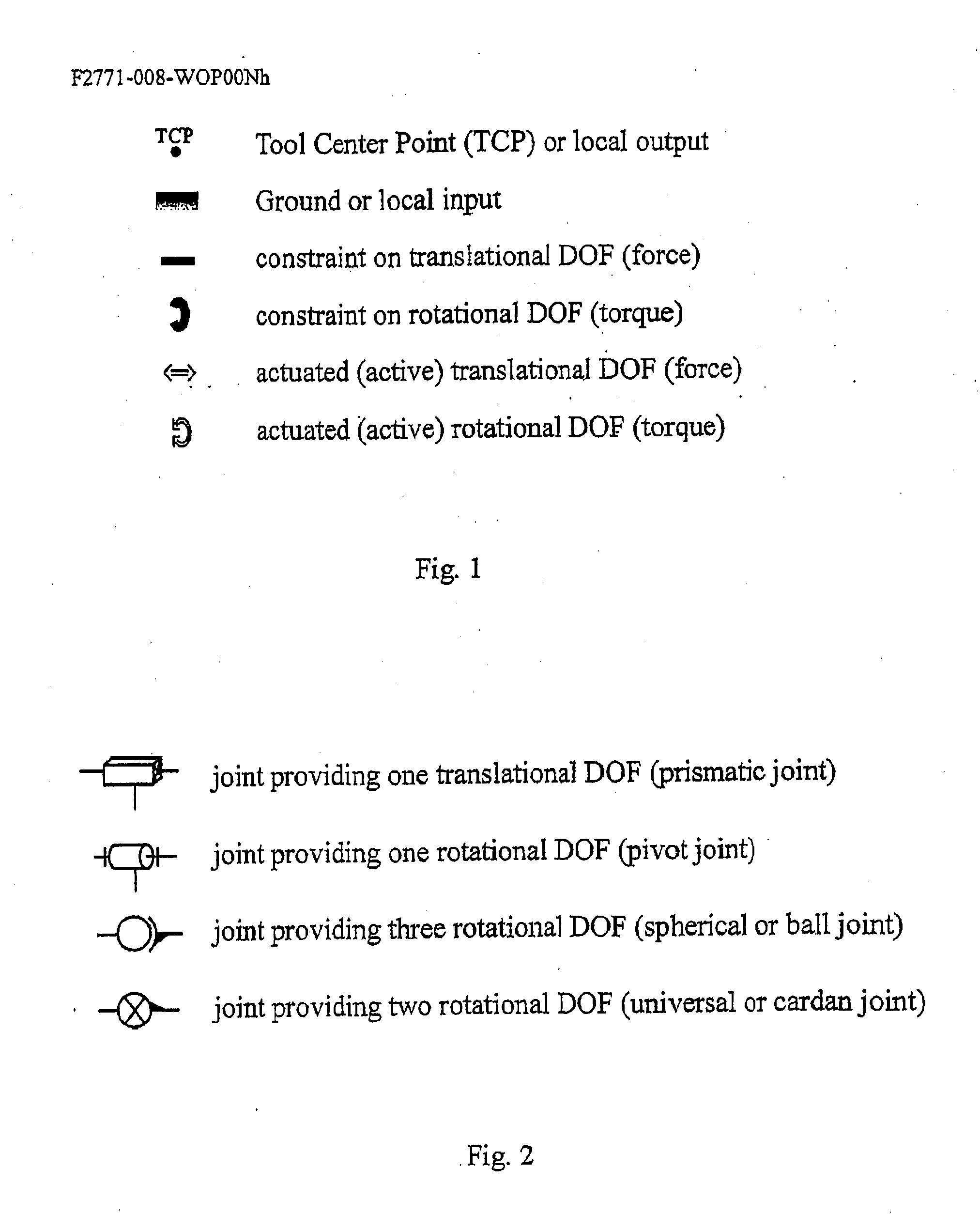
[0069]In the device of the present invention, the first kinematics bond may comprises at least one of the following: a jointed link; a jointed parallelogram; a pivot joint; a pivot joint with remote rotation axis; a universal joint; a cardan joint; a spherical joint; a timing belt; a cable; a wire; a string; a tendon; a band; gears; a deformable solid state hinge; a deformable beam; a deformable bar; a deformable membrane; an elastic constraining element; a ball bearing; a friction bearing; surface portions in contact.

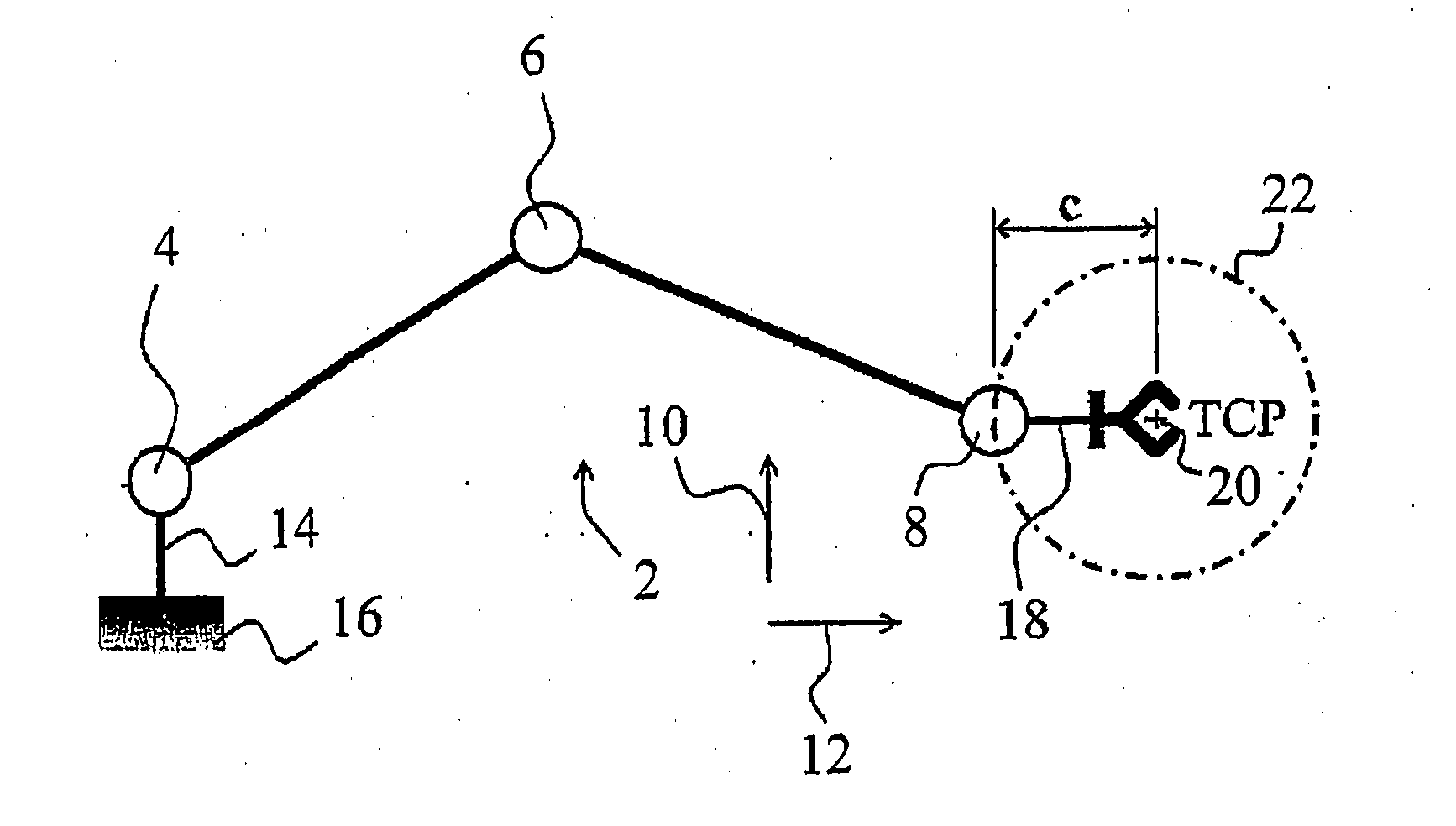
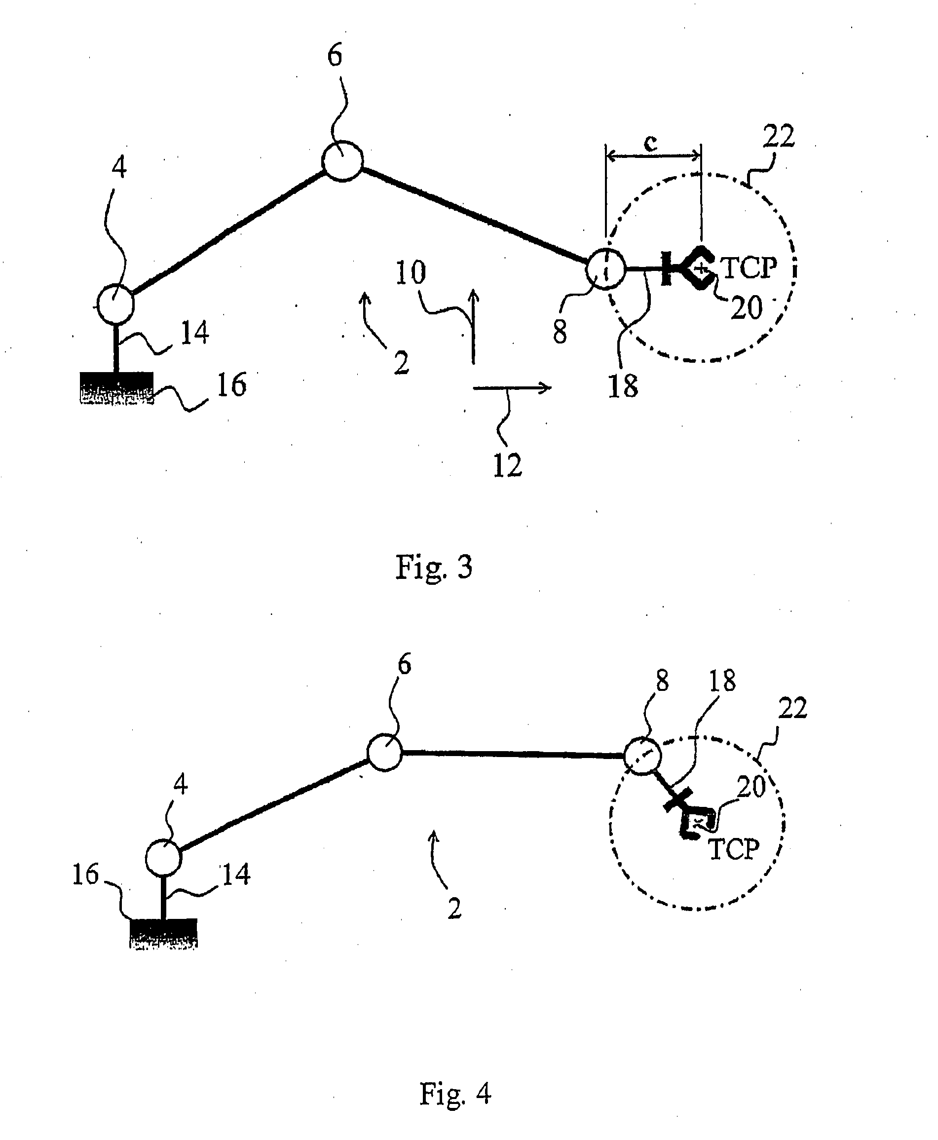
[0070]In the device of the present invention, the output member may comprises at least two rotational degrees of freedom having rotation axes, each of which being spatially offset with respect to corresponding rotation axis associated to the rotational degrees of freedom of the intermediate member provided to i...


PUM


Abstract

A device for the relative movement between an input member and an output member, the device comprising an input member (100); an output member (108); an intermediate member (104) coupling the input member (100) and the output member (108); a first kinematics bond (102) coupling the intermediate member (104) and the input member (100); the first kinematics bond (102) providing at least two rotational degrees of freedom; and a second kinematics bond (106) coupling the intermediate member (104) and the output member (108), the second kinematics bond (106) being adapted to transmit rotational motions between the intermediate member (104) and the output member (108) and to offset rotation axes of at least two rotational degrees of freedom of the output member (108).

Description

FIELD OF THE INVENTION[0001]The present invention generally relates to devices providing relative movements between an input member and an output member.BACKGROUND OF INVENTION[0002]Manipulators, robots, haptic devices or more generally devices for relative movement of two elements with full motion capability in space need to provide six Degrees Of Freedom (DOF) at their moveable output member or end effector (usually with respect to the ground or base), which corresponds to the maximum spatiality of a rigid body in space. Three DOF are needed to perform translations in space and three DOF for rotations.[0003]For most applications, only a subset of these six DOF is needed. So, the complexity and cost of the robotic structure can be reduced. Further, performance may be increased by choosing a design with fewer than six active (or powered) DOF, the motions along the remaining non-powered DOF being rigidly constrained (e.g. to ground or a fixed structure), or left free to move (or comp...

Claims


Application Information

Patent Timeline
Patent Type & Authority Applications(United States)
IPC IPC(8): G05G1/00
CPCB25J9/106B25J9/1065Y10T74/20B25J9/0072B25J17/0266
Inventor HELMER, PATRICK
Owner FORCE DIMENSION S A R L
Why Eureka
Try Eureka