Heat exchanger

a technology of heat exchanger and circulating air, which is applied in the direction of machines/engines, combustion air/fuel air treatment, light and heating apparatus, etc., can solve the problems of large amount of condensation accumulation, achieve easy and cost-effective integration, and improve the delivery head in the condensation channel. , the effect of low static pressur

Inactive Publication Date: 2010-12-02
MAHLE INT GMBH
View PDF14 Cites 47 Cited by
  • Summary
  • Abstract
  • Description
  • Claims
  • Application Information

AI Technical Summary

Benefits of technology

[0009]In an alternative or additional embodiment, the structure can include a modulation of an edge of at least one of the tubes on the outlet side, thereby improving atomization of the condensation driven by the gas flow in the tube at the edge of the tube. In a first possible detail design, the edge modulation may involve an upward bending of the edge, either an upward bending on only one side or also on two sides. By upward bending of the outlet edge, the flow cross-section for the gas flow is reduced so that a greater flow velocity forms locally which improves atomization of the condensation film. At the same time, an upward bending in a suitable direction may cause the gas flow to be deflected in the direction of the collector box outlet. This effect is intensified by also bending up the other outlet edge of the tube, which is usually designed as a flat tube. In an alternative or additional detail design, the tube edge may have a corrugation, for example in the manner of a crenellation or sinusoidal waves. A corrugation of this type generally improves the atomization of the condensation at the edge of the tube.
[0017]In an embodiment, the projection of the turbulence member is provided with a bend, in particular in the direction of the outlet. This makes it possible to further improve the atomization of the condensation and equalize the gas flow in the collector box. The weighted projections of the turbulence members may thus perform the same or a similar function as a conducting member for influencing the gas flow in the collector box, for example to improve transport of a condensation film on a collector box wall in the direction of the outlet.

Problems solved by technology

When cooling charge air, large amounts of condensation may accumulate in general and particularly in connection with an exhaust gas recirculation system.

Method used


Image

  • Heat exchanger
  • Heat exchanger
  • Heat exchanger

Examples


Embodiment Construction

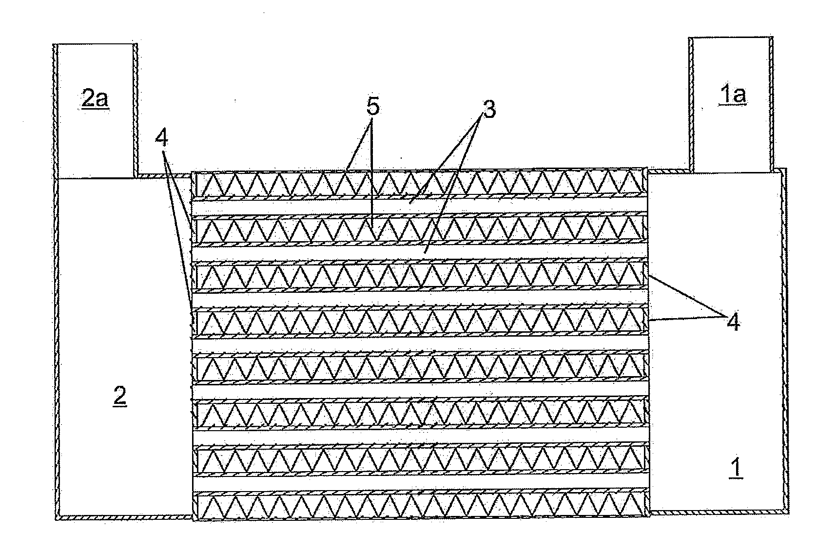
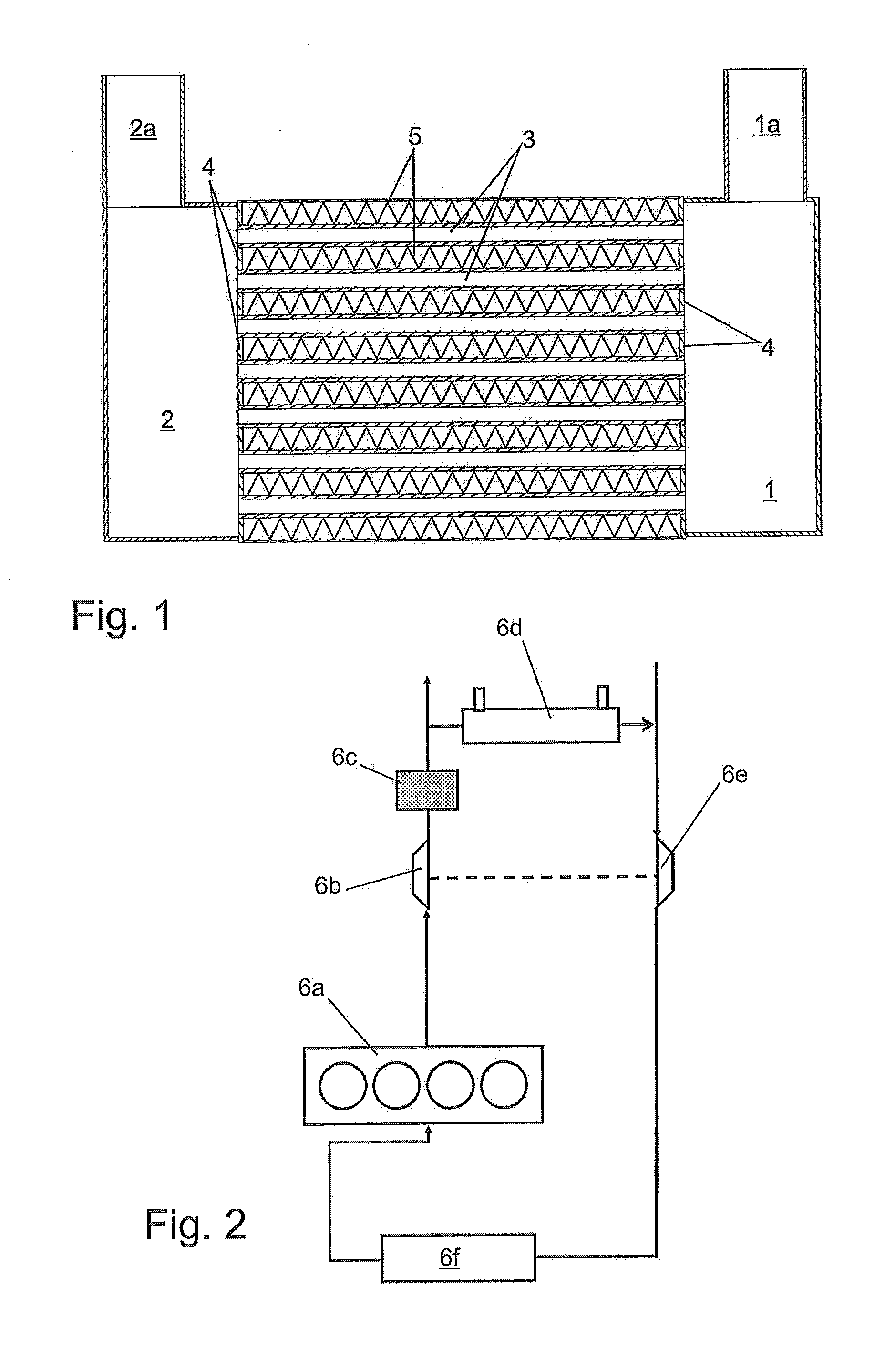
[0026]A heat exchanger designed as a charge air cooler according to the prior art (FIG. 1) comprises a collector box 1 on the input side having an inlet 1a, a collector box 2 on the output side having and outlet 2a and a plurality of tubes 3 extending in the horizontal direction between collector boxes 1, 2 in the form of flat aluminum tubes. Tubes 3 are accommodated in bases 4 of the collector boxes and terminate flush therewith.

[0027]Fins 5, through which cooling air flows (perpendicular to the plane of the drawing), are provided between flat tubes 3. The charge air cooler according to FIG. 1 is a direct charge air cooler for cooling using airstream. In principle, an indirect charge air cooler or the like may also be provided. The gas flow flows from inlet 1a through collector box 1 on the input side, is distributed to tubes 3, collected again in collector box 2 on the output side and then flows to outlet 2a. Condensation may accumulate, in particular, on the insides of tubes 3, t...


PUM


Abstract

A heat exchanger, in particular a charge air cooler or an exhaust gas cooler for an internal combustion engine, comprising a plurality of essentially parallel tubes and at least one collector box on the output side, the tubes each emptying into the collector box on the output side, and a gas flow flowing from the tubes into the collector box and from the collector box into an outlet of the collector box, a structure for interacting with the gas flow being provided at least one of the tubes or collector box, a condensation being transported to the outlet with the aid of the structure.

Description

[0001]This nonprovisional application claims priority under 35 U.S.C. §119(a) to German Patent Application No. DE 10 2009 022 986.8, which was filed in Germany on May 28, 2009, and which is herein incorporated by reference.BACKGROUND OF THE INVENTION[0002]1. Field of the Invention[0003]The invention relates to a heat exchanger, in particular a charge air cooler or an exhaust gas cooler for an internal combustion engine.[0004]2. Description of the Background Art[0005]Air charge coolers and exhaust gas coolers are known from automotive engineering practice, in which the compressed gas to be cooled is conducted through a plurality of exchanger tubes which extend between two collector boxes. In principle, a certain amount of liquid condensation accumulates due to the cooling of the gas flow. A large amount of condensation accumulates in systems such as a low-pressure exhaust gas recirculation system, since the gas flow supplied to the charge air cooler is made not only of air alone, but...

Claims


Application Information

Patent Timeline
Patent Type & Authority Applications(United States)
IPC IPC(8): F01P9/00
CPCF28D21/0003F28F2009/029F28D2021/0082F28F17/005F28F3/025F28F9/0265F28F9/0282F28D7/1684F28F9/0268F28F2250/02
Inventor STEURER, HANS-ULRICHGESKES, PETERSAUMWEBER, CHRISTIAN
Owner MAHLE INT GMBH
Why Eureka
Try Eureka