Hydraulic Oilfield Lift Pump

a technology of hydraulic oilfield and lift pump, which is applied in the direction of piston pump, fluid removal, borehole/well accessories, etc., can solve the problem of low effective electric rate, and achieve the effect of reducing system stress and reducing large load fluctuations

Inactive Publication Date: 2010-12-02
NAT OILWELL VARCO LP
View PDF16 Cites 23 Cited by
  • Summary
  • Abstract
  • Description
  • Claims
  • Application Information

AI Technical Summary

Benefits of technology

[0015]During the ‘down’ stroke, the pressurized fluid from the hydraulic power unit is applied only to the ‘rod’ ends of the double acting hydraulic cylinders. The combination of the weight of the load and this hydraulic pressure on the top end of the cylinder causes all the cylinders to retract. This in turn forces the hydraulic fluid on the cap ends of the double acting cylinders back into the accumulators—and therefore filling them. The relative horsepower required for each of t

Problems solved by technology

Furthermore, the lower peak power consumption may allow for a lower effective electric rate, as in many lo

Method used


Image

  • Hydraulic Oilfield Lift Pump
  • Hydraulic Oilfield Lift Pump
  • Hydraulic Oilfield Lift Pump

Examples


Embodiment Construction

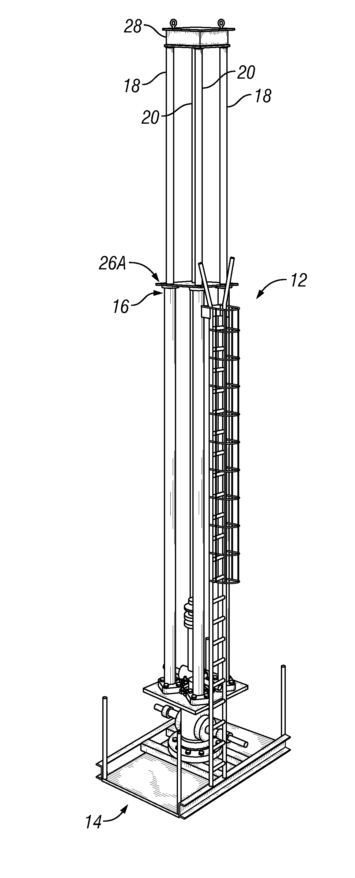
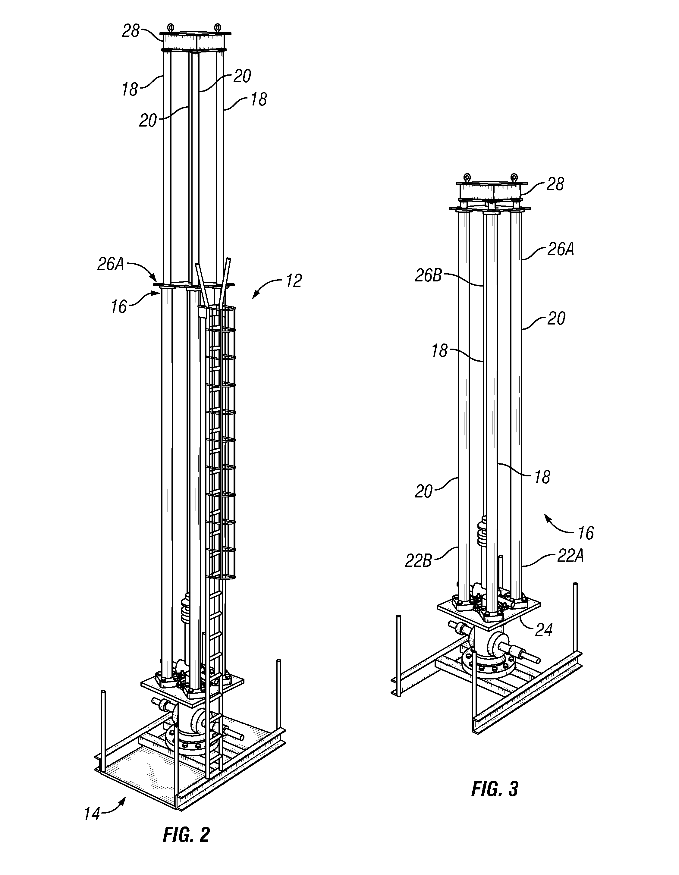
[0022]Referring now to FIGS. 2 and 3; the hydraulically driven surface oil well pumping unit 12 of the present invention comprises a base portion 14, including a hydraulic power unit (not shown) and a mast portion 16 comprising a pair of single acting hydraulic cylinders 18 and a pair of double acting hydraulic cylinders 20. FIG. 2 shows the hydraulic cylinders 18, 20 of the hydraulically driven oil field pumping unit 12 fully extended, and FIG. 3 shows the mast portion 16 separated from the rest of the oilfield pumping unit 12 of FIG. 2 with the hydraulic cylinders 18, 20 fully retracted. The new oil well pumping unit 12 of the present invention is useful in reciprocating a “load” in the wellbore; particularly a load which is substantially higher as the load is being raised, than when the load is being lowered—as is typically the case when pumping oil in an oil well.

[0023]The cap ends 22a and 22b of the hydraulic cylinders 18, 20 are shown mounted to a common rigid base plate 24. T...


PUM


Abstract

A vertically orientated hydraulically driven oilfield lift pump unit having a simplified hydraulic system. The system uses a pair of single acting hydraulic cylinders in tandem with a pair of double acting hydraulic cylinders interacting with hydraulic accumulators to provide an energy efficient, robust hydraulic system design with a minimum number of components.

Description

[0001]This application claims priority from U.S. provisional patent application Ser. No. 61 / 183,264, filed on Jun. 2, 2009, which is incorporated herein by reference.BACKGROUND OF THE INVENTION[0002]1. Field of the Invention[0003]This invention relates to lift pumps suitable for producing hydrocarbons and other liquids from the earth. In particular, this invention is drawn to a very long stroke hydraulically operated lift pump using a combination of single and double acting hydraulic cylinders that are actuated with an energy efficient hydraulic fluid accumulator system.[0004]2. Description of the Related Art[0005]Hydraulically operated Oilfield lift pumping units are well known and have been used in the industry for many years. Typically, these units mimic the non-hydraulic mechanical ‘walking beam’ design similar to the pumping unit 10 illustrated in FIG. 1. These conventional units are more commonly driven directly by electric motors through gear boxes, but many are also hydrauli...

Claims


Application Information

Patent Timeline
IPC IPC(8): E21B43/00F04B47/08
CPCF04B47/04E21B43/126
Inventor LORIMER, GERRY L.BLAQUIERE, DENIS J.
Owner NAT OILWELL VARCO LP
Why Eureka
Try Eureka