Vehicle with a variable driver position

a technology of driver position and vehicle, which is applied in the direction of steering controls, steering parts, vehicle mounted steering controls, etc., can solve the problems of high rate of machine operator injury, poor seating standard of machine operators, and undesirable body vibration, shock load and fatigu

Inactive Publication Date: 2010-12-02
PWGK HLDG
View PDF16 Cites 53 Cited by
  • Summary
  • Abstract
  • Description
  • Claims
  • Application Information

AI Technical Summary

Benefits of technology

[0017]In a preferred embodiment, the vehicle is configured with a selectable rotation mode wherein, when the rotation mode is selected, the steering control is operable to effect, and determine the direction of, rotation of said group of vehicle components relative to the platform.
[0018]In a preferred embodiment, the vehicle includes a pair of driver foot safety actuators, the vehicle being configured to prevent rotation of said group of vehicle components unless said safety actuators are actuated together. Preferably, the actuation of said safety actuators at the same time selects said rotation mode.
[0019]Also In a preferred embodiment, the vehicle includes a parking brake which is adapted to be automatically activated to prevent movement of the vehicle in either of said primary and secondary directions while said group of vehicle components is being rotated relative to said vehicle platform.
[0020]In a preferred embodiment, the vehicle includes vehicle drive means for driving the vehicle in said primary and secondary directions, and a sensor control for sensing if said group of vehicle components is neither in said first position nor said second position, and in that case for deactivating said vehicle drive means to prevent the vehicle from being driven in either of said primary and secondary directions. Preferably, said sensor control is configured to sense if said group of vehicle components is in either said first position or said second position, and thereupon to enable activation of said vehicle drive means.
[0021]In a preferred embodiment, the vehicle includes controls for selecting a forward direction mode for causing the vehicle to be driven in a forward direction, or a reverse direction mode for causing the vehicle to be driven in a reverse direction which is opposite to the forward direction, wherein said sensor control is adapted to set the forward direction to correspond to the primary direction when the driver's seat is facing in the primary direction and to the secondary direction when the driver's seat is facing in the secondary direction.

Problems solved by technology

In the underground mining industry, there is a high rate of injury to machine operators which may be attributed to a combination of the harsh environment and equipment which is not entirely suitable for this environment.
Indeed, common contributors to operator injury include rough roadway conditions and the poor standard of seating for the operators of these machines.
This results in undesirable body vibration, shock loads and fatigue.
These problems are experienced in particular by drivers of underground mining vehicles, due largely to the poor ergonomics of the drivers' seating positions and the relative positions of the vehicles' controls.
This problem is exacerbated by the fact that in many underground mining scenarios, due to the extremely limited width of underground roadways, vehicles are required to travel forwards when proceeding in one direction along a roadway, and rearwards when proceeding in the opposite direction along the road, as there is insufficient space for such vehicles to turn around.
However, this configuration has various disadvantages.
One disadvantage is that only a single steering wheel and set of controls is provided (other than the foot pedals) and these are positioned at right angles to the direction in which the two seats face.
This provides for poor ergonomics and significant lack of comfort for the driver.
In addition, the cramped space makes it awkward and inconvenient for the driver to move from one seat to the other when the vehicle's direction of travel is to be changed.
Thus, the driver is required to use different hands for operating the steering wheel and controls depending on the direction of travel, and it is difficult and counter-intuitive for drivers to adapt to the changing relative position of these controls The need to replicate the foots pedals also gives rise to an undesirable expense.
Disadvantages of this configuration include that the operator must turn his head through substantially 90 degrees in order to look in the direction of travel.
This seating position, together with the harsh and bumpy terrain can cause discomfort and injury to the driver.

Method used


Image

  • Vehicle with a variable driver position
  • Vehicle with a variable driver position
  • Vehicle with a variable driver position

Examples


Embodiment Construction

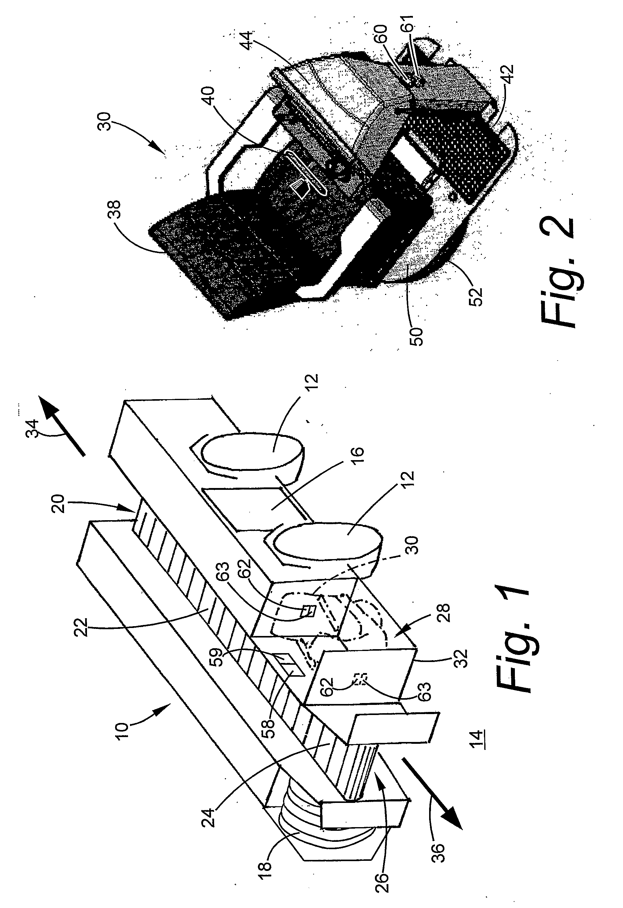
[0032]Referring to FIG. 1, there is shown a wheeled underground mining vehicle 10, which, in the present example, is in the form of a coal shuttle. The vehicle 10 has four wheels 12 by which the vehicle is supported on a roadway surface 14. In the present example, the roadway is a narrow roadway leading to a coal-mining face (not shown).

[0033]The vehicle 10 has an electrical traction control drive 16 for driving the vehicle via the wheels 12. The traction control drive 16 is connected, by a suitable cable, to an electrical power source for providing power to the traction control drive (the cable and power source not being shown). A reel 18 is provided on the vehicle 10, onto which the cable can be wound as the vehicle 10 approaches the power source (in which event a shorter length of cable between the power source and vehicle is required) and from which the cable can be unwound as the vehicle moves away from the power source (in which event a greater length of cable is required).

[00...


PUM


Abstract

There is disclosed a wheeled vehicle (10) adapted to be driven in a primary direction or an opposite secondary direction. The vehicle has a vehicle platform (32), and a group of vehicle components rotatably mounted on the platform which are rotatable as a group through 180 degrees relative to the platform. The group of components includes a driver's seat (38), steering wheel (40), foot pedals (42) and instrument console (44). Rotation of the group of components enables the driver's seat (and hence the driver) to face in the primary direction or secondary direction.

Description

FIELD OF THE INVENTION[0001]This invention relates to a vehicle with a variable driver position.BACKGROUND TO THE INVENTION[0002]In the underground mining industry, there is a high rate of injury to machine operators which may be attributed to a combination of the harsh environment and equipment which is not entirely suitable for this environment. Indeed, common contributors to operator injury include rough roadway conditions and the poor standard of seating for the operators of these machines. This results in undesirable body vibration, shock loads and fatigue. These problems are experienced in particular by drivers of underground mining vehicles, due largely to the poor ergonomics of the drivers' seating positions and the relative positions of the vehicles' controls.[0003]This problem is exacerbated by the fact that in many underground mining scenarios, due to the extremely limited width of underground roadways, vehicles are required to travel forwards when proceeding in one direc...

Claims


Application Information

Patent Timeline
Patent Type & Authority Applications(United States)
IPC IPC(8): B60K26/00
CPCB60K26/00B60N2/143E21F13/00B62D1/02B60T7/06
Inventor RYAN, JOHNMOORE, DAMIENCHAPMAN, MARKVOUGHT, GRAHAM
Owner PWGK HLDG
Why Eureka
Try Eureka