
Hydraulic variable shock absorber with flow control valve

a technology of variable damping and flow control valve, which is applied in the field of valves, can solve the problems of loss of control, complex and costly construction of actuators, and user or the manufacturer himself being unable to vary the damping degree, and achieves the effect of high degree of hydraulic fluid tightness, simple production, and high sensitivity for adjusting

Active Publication Date: 2010-12-02
MAGNETI MARELLI COPAF CO FAB DE PECAS
View PDF6 Cites 3 Cited by
  • Summary
  • Abstract
  • Description
  • Claims
  • Application Information

AI Technical Summary

Benefits of technology

[0014]Due to the constructive complexity of the known prior art flow control valves, which are associated with electromagnetic actuators of the on-off type with limiting operation, or of the costly progressive or stepped operation type which is subject to leakages and presents low-sensitive adjustment, it is an object of the present invention to provide a flow control valve for hydraulic shock absorbers presenting a simple, strong, and leak tight construction, which can be adequately operated by different actuators also presenting a simple construction and which are adequate to the provision of a fine adjustment of the control valve operational positions defined by a closed position and a plurality of open positions, for obtaining respective behaviors for the shock absorber, which differ from one another as a result of a fine adjustment of the control valve operation.
[0016]It is also an object of the present invention to provide a control valve of the type defined above and whose operation allows obtaining a decreasing pressure loss of the hydraulic fluid with the increase of its flow through the valve.
[0017]It is also an object of the present invention to provide a control valve with the characteristics defined above and which leads to a greater comfort of the passengers of an automobile vehicle, to a better behavior of the vehicle running on roads having a smooth surface or presenting different degrees of surface irregularities, and also to greater stability and safety for vehicles such as buses and trucks under low or high weight.
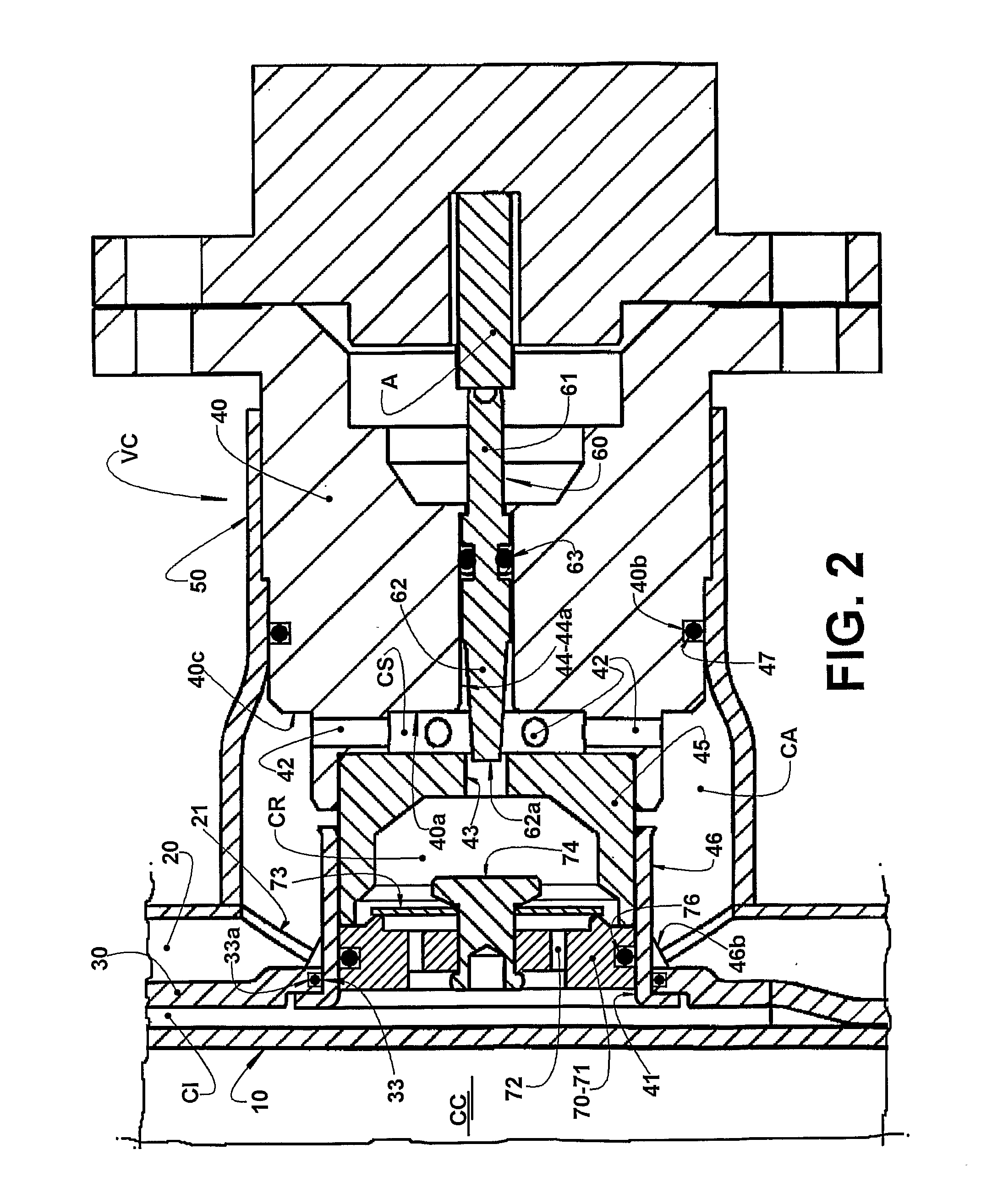
[0020]The control valve construction defined above permits it to be easily incorporated to the shock absorber structure and also driven between a closed position and a fully open position, passing through different partially open positions, by means of an actuator which can present different strong constructions which are relatively simple to be produced. The shutter pin construction permits it to be reliably and controllably displaced to a high number of operational positions, each corresponding to an operational condition of the shock absorber, which fact leads to a higher sensitivity for adjusting or calibrating the shock absorber.
[0021]The control valve construction and its mounting in the hydraulic shock absorber, as proposed by the present invention, also allows obtaining a high degree of tightness for the hydraulic fluid and, accordingly, a better and more precise control over the shock absorber behavior.

Problems solved by technology

The user or the manufacturer himself cannot vary the degree of damping after the manufacture of the shock absorber.
However, the construction of these actuators is complex and costly.
Even the attempts for providing control valves with their actuation defined by the controlled displacement of a shutter have presented difficulties for avoiding even small leakages of the hydraulic fluid, and also for providing an adequate control having high sensitivity in relation to the responses to be obtained from the shock absorber when submitted to different operation conditions regarding the speed of the vehicle and the load thereon, and also the conditions of the road on which the vehicle is running.
The hydraulic fluid leakages between the valve parts and between the valve and the shock absorber reservoir, leads to pressure loss, influencing the behavior of the shock absorber, particularly in low speeds of the vehicle, which can cause loss of control.
The shutters of the known solutions have reduced course, which provokes, even with small displacements, substantial alterations in the behavior of the shock absorber, making difficult to obtain fine variations in the operation of the shock absorber.

Method used


Image

  • Hydraulic variable  shock absorber with flow control valve
  • Hydraulic variable  shock absorber with flow control valve
  • Hydraulic variable  shock absorber with flow control valve

Examples


Embodiment Construction

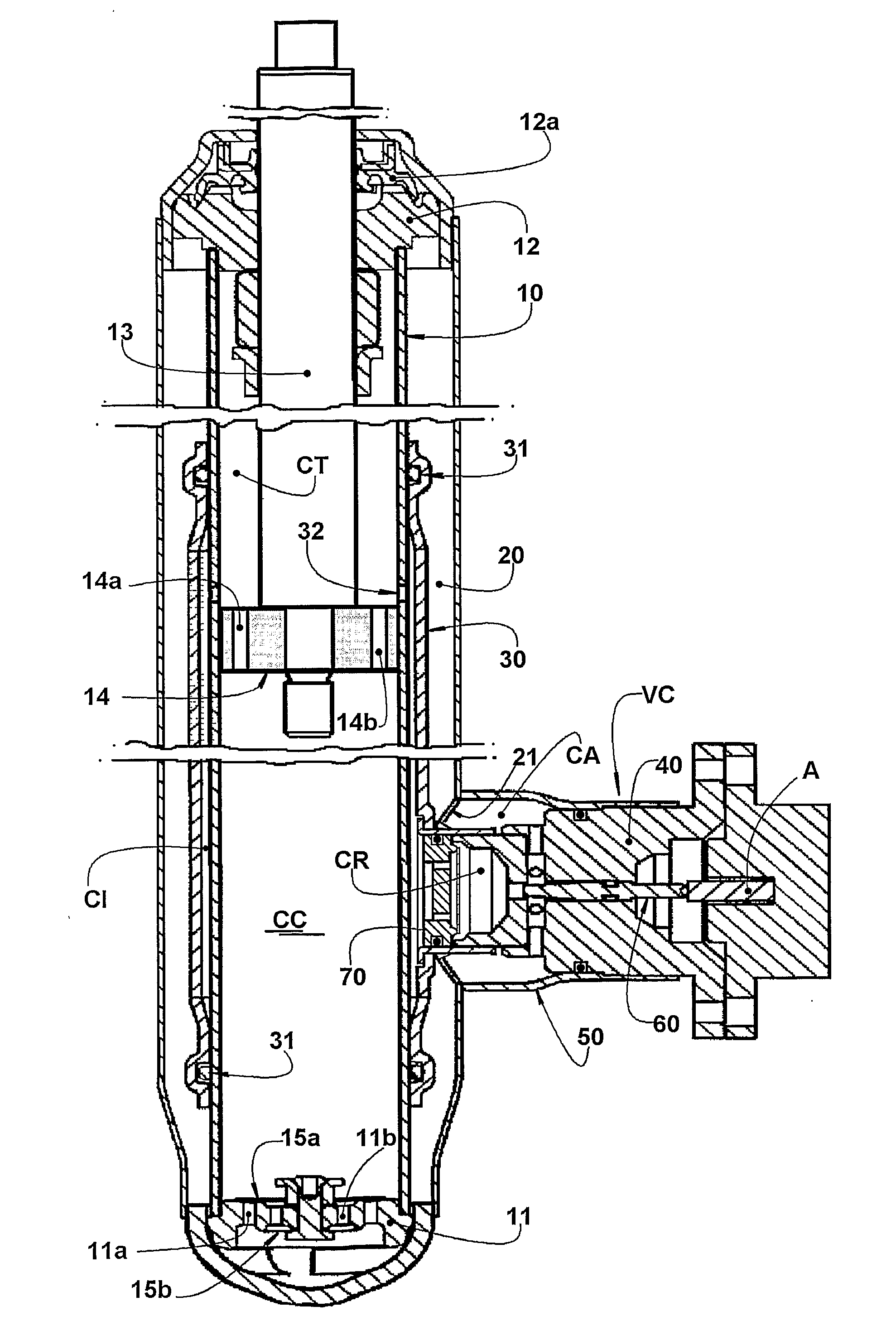
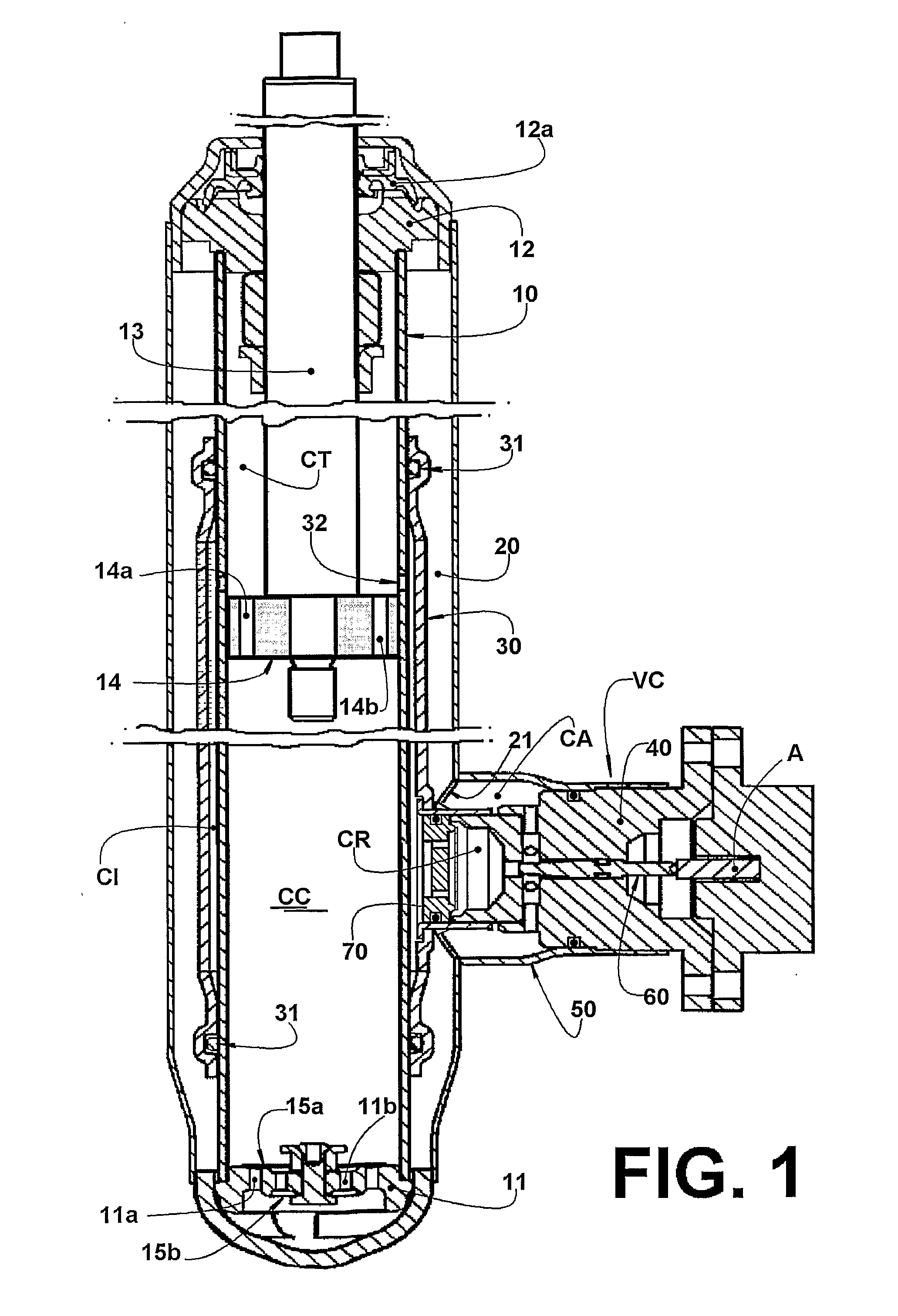
[0028]As already previously mentioned, the invention generally refers to double-acting hydraulic shock absorbers, to be used, for example, in the suspension of wheeled vehicles and which comprise a generally cylindrical pressure tube having a lower end closed by a valve plate 11 and with the upper end closed by an annular plate 12 carrying a seal 12a, through which slides a rod 13 having an end external to the pressure tube 10 and an end internal to the latter and coupled to a piston 14, which is axially displaced in the interior of the pressure tube 10, during the operation of the shock absorber.

[0029]In a known manner, the piston 14 divides the interior of the pressure tube 10 in a compression chamber CC, adjacent to the valve plate 11, and in a traction chamber CT, adjacent to the annular plate 12.

[0030]The valve plate 11 is provided with two sets of axial passages 11a, 11b, communicating the interior of the compression chamber CC with the interior of a hydraulic fluid reservoir ...


PUM


Abstract

The control valve is applied to a shock absorber, which comprises: a pressure tube (10); a piston (14) dividing the pressure tube (10) in compression and traction chambers (CC, CT) communicating with each other through the piston (14); a hydraulic fluid reservoir (20) provided with a selective bidirectional fluid communication with the compressor chamber (CC). The control valve (VC) communicates the traction chamber (CT) with the reservoir (20) and comprises a tubular body (40) provided with at least one radial passage (41) opened to the interior of the tubular body (40) and to the reservoir (20); a shutter pin (60) to be axially displaced within the tubular body (40), between a closing position and different open positions of the control valve (VC) for communicating the traction chamber (CT) with the reservoir (20); and an actuator means (A) for axially displace the shutter pin within the tubular body (40).

Description

FIELD OF THE INVENTION[0001]The present invention refers to a valve to be applied to a hydraulic shock absorber, particularly a hydraulic shock absorber for wheeled transport vehicles, in order to allow controlling the hydraulic fluid flow in the shock absorber and, thereby, the variation in the damping force to be produced by the shock absorber, in both the compression and traction directions.PRIOR ART[0002]There are well known from the prior art the double-acting hydraulic shock absorbers, usually employed in suspension systems of automobile vehicles and which comprise a pressure tube inside which a piston is slidably mounted, dividing the pressure tube in an inferiorly disposed compression chamber and in a superiorly disposed traction chamber. The pressure tube has a lower end closed by a valve plate provided with a pair of passages, one of which housing a discharge valve and the other an admission valve, the upper end of the pressure tube being closed by a sealing annular plate,...

Claims


Application Information

Patent Timeline
Patent Type & Authority Applications(United States)
IPC IPC(8): F16F9/34F16F9/342F16F9/10
CPCF16F9/461F16F9/342
Inventor VANNUCCI, SERGIO NELO
Owner MAGNETI MARELLI COPAF CO FAB DE PECAS
Learn More