Pressurized plasma enhanced reactor

Active Publication Date: 2010-12-02
INENTEC
View PDF43 Cites 8 Cited by
  • Summary
  • Abstract
  • Description
  • Claims
  • Application Information

AI Technical Summary

Benefits of technology

[0016]In addition to sealing the electrodes themselves, the present invention provides a method for sealing all of the penetrations into the processing chamber to prevent the escape of gasses, organic materials, vitreous glass, and metals, all of which are c

Problems solved by technology

Operation of gasification and vitrification systems at elevated pressures provides numerous advantages over operating at lower pressures, but it presents problems which were heretofore not encountered in the prior art.
As yet another further result,

Method used


Image

  • Pressurized plasma enhanced reactor
  • Pressurized plasma enhanced reactor
  • Pressurized plasma enhanced reactor

Examples


Example

[0023]For the purposes of promoting an understanding of the principles of the invention, reference will now be made to the embodiments illustrated in the drawings and specific language will be used to describe the same. It will nevertheless be understood that no limitations of the inventive scope is thereby intended, as the scope of this invention should be evaluated with reference to the claims appended hereto. Alterations and further modifications in the illustrated devices, and such further applications of the principles of the invention as illustrated herein are contemplated as would normally occur to one skilled in the art to which the invention relates.

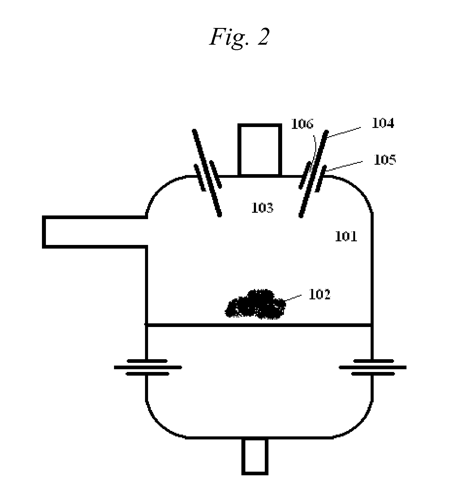
[0024]As shown in FIG. 2, one embodiment of the present invention is a processing chamber 101 for converting organic material 102 to useful gas products 103. The processing chamber has at least one port 104, and at least one electrode 105 penetrating the processing chamber 101 through the port 104. Organic material 102 and oxyge...


PUM


Abstract

The present invention is a vitrification and gasification system that operates at elevated pressures. The system includes a processing chamber having numerous penetrations, and seals for effectively sealing the penetrations to the processing chamber.

Description

RELATED APPLICATIONS[0001]This invention claims priority to U.S. Provisional Application No. 61 / 181099 filed May 26, 2009.TECHNICAL FIELD[0002]This invention relates to gasification and waste treatment systems. More specifically, this invention relates to high temperature systems used to convert organic matter to useful fuels such as synthesis gas.BACKGROUND OF THE INVENTION[0003]There have been a number of examples of apparatus and methods for converting organic matter into useful fuel. For example, U.S. Pat. No. 5,666,891 title “Arc Plasma-Melter Electro Conversion System for Waste Treatment and Resource Recovery” describes a system that combines joule heating and plasma heating in a process chamber. In this system, organic materials can be converted into hydrogen rich gasses which may be used as fuels, or which may be converted into other fuels, such as liquid methanol.[0004]The advantages of these systems are readily apparent, as they allow waste products, which normally must be...

Claims


Application Information

Patent Timeline
IPC IPC(8): H05H1/24B01J19/08C01B3/02
CPCC10J3/18C10J3/57C10J3/84C10J2200/09C10J2200/12C10J2300/1238F28D19/02F23G5/085Y02E20/12C10J3/78C10J3/86F16J15/16C10J2300/1884Y02P20/10B01J7/00B01J19/081B01J2219/0879B01J2219/0898C01B3/02C10J3/82F16J15/46
Inventor BATDORF, JAMESLAMAR, DAVIDOLSON, DIETER
Owner INENTEC
Why Eureka
Try Eureka