While these types of diaper pails have had relatively good commercial success, it has been found that the existing designs still have drawbacks that could be improved upon.
For example, it has been found that the existing designs still do not effectively prevent the escape of odors.
Providing a seal around the housing and between the upper receptacle assembly and the lower pail is not a difficult task, as these components do not move relative to each other during normal use and the seals are loaded only in compression, but, this arrangement does require multiple seals and additional related parts as well as additional cost and complexity.
On the other hand, the provision of a substantially airtight seal between moving components is not as simple, and the most difficult place to provide a seal is between the moving surfaces of the drum and the
lower half of the drum housing.
However, in practice, foam sheets and other ring seals have not been ideal.
One issue is that the hook and loop tabs on diapers are prone to catch on the edges of the seal or on the face of the seal itself, and become lodged between the drum and the housing.
In such an event, where two surface are moving relative to each other but are constrained to a constant separation, a great deal of compressive and
shear force is generated between the rotating and fixed surfaces often destroying the foam or other soft seal.
Another issue is that the sheet foam seals are expensive to manufacture and required the use of soft foam with a top fabric layer to reduce friction.
Stamping these seals from roll stock created a great deal of waste.
Further, the foam seals have to be properly positioned and glued in place, or carefully positioned in place, requiring skilled labor.
O-ring seals also are not ideal.
They are hard to hold in place and are easily displaced during use.
If the O-ring is too hard, the seal does not properly conform to the surface irregularities between the drum and the housing.
If the O-ring is soft enough to conform to the drum surface, then the
coefficient of friction is too high and the drum is hard to turn.
Odor eliminating devices need to be replaced frequently, replacements are not always kept in the house, and are costly, driving up the ongoing costs of use of the device.
Another drawback to an electro-
mechanical system is the reliance on
electricity, the use, replacement and cost of batteries, or that the pail must be located near an outlet to function.
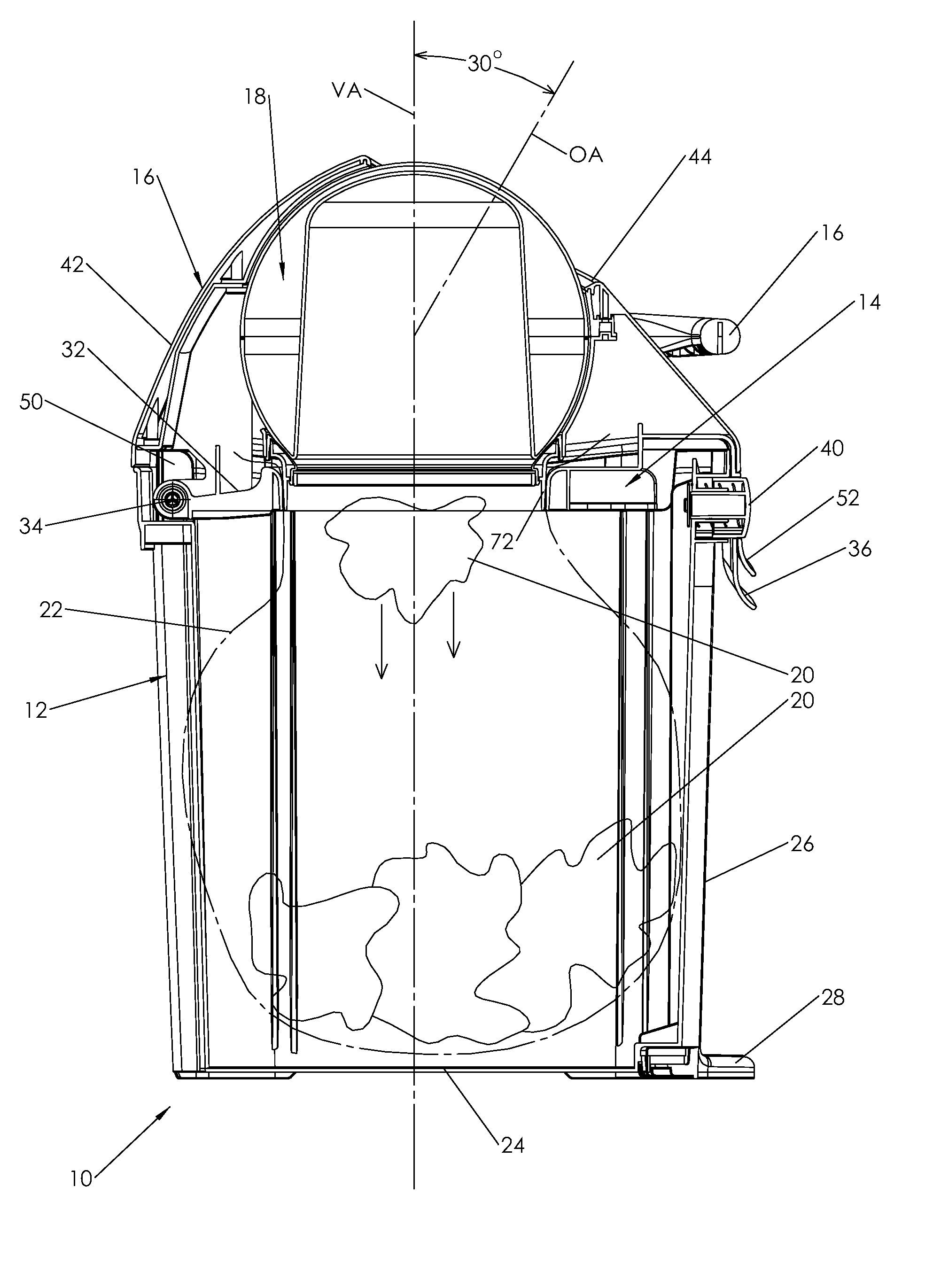
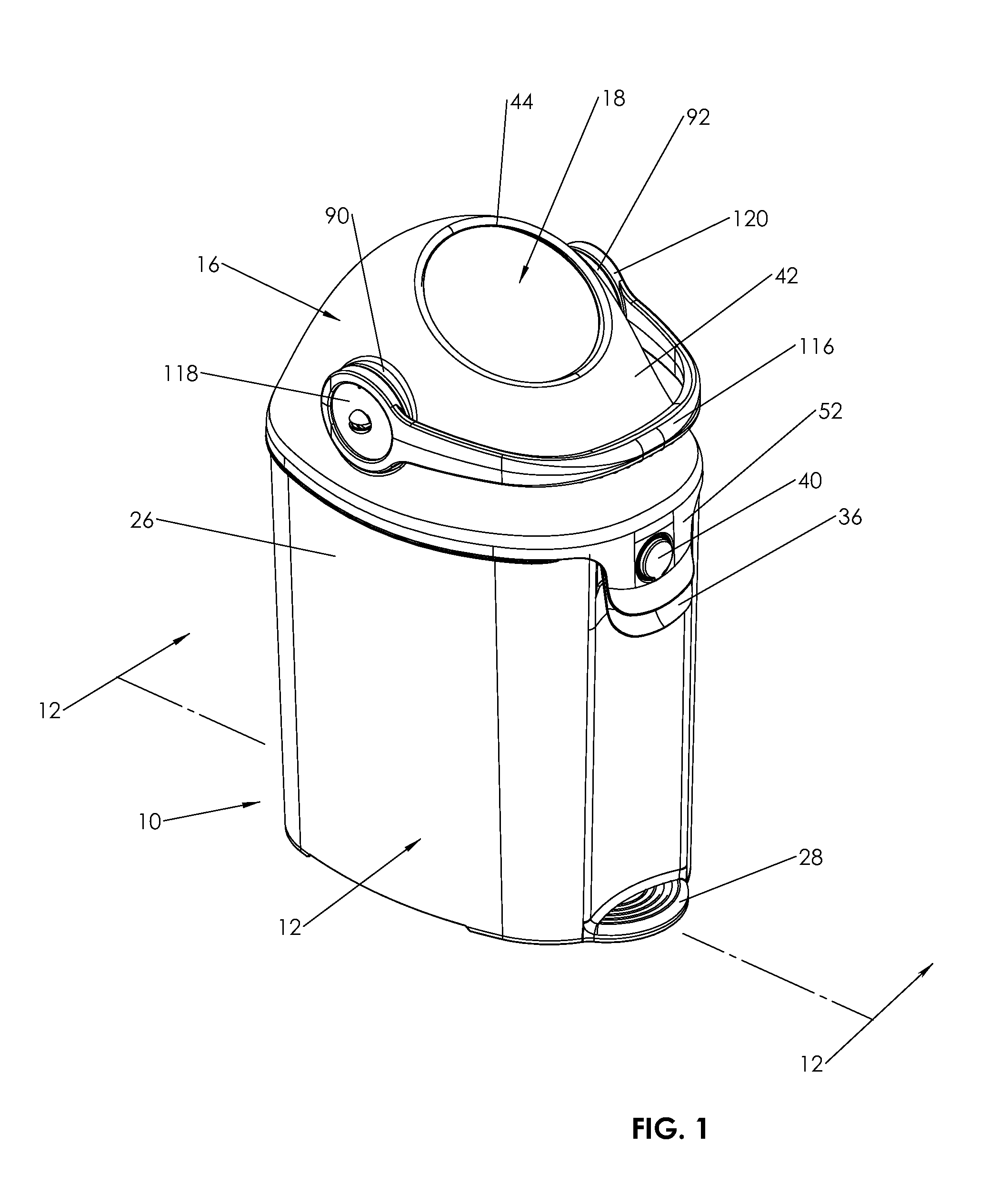
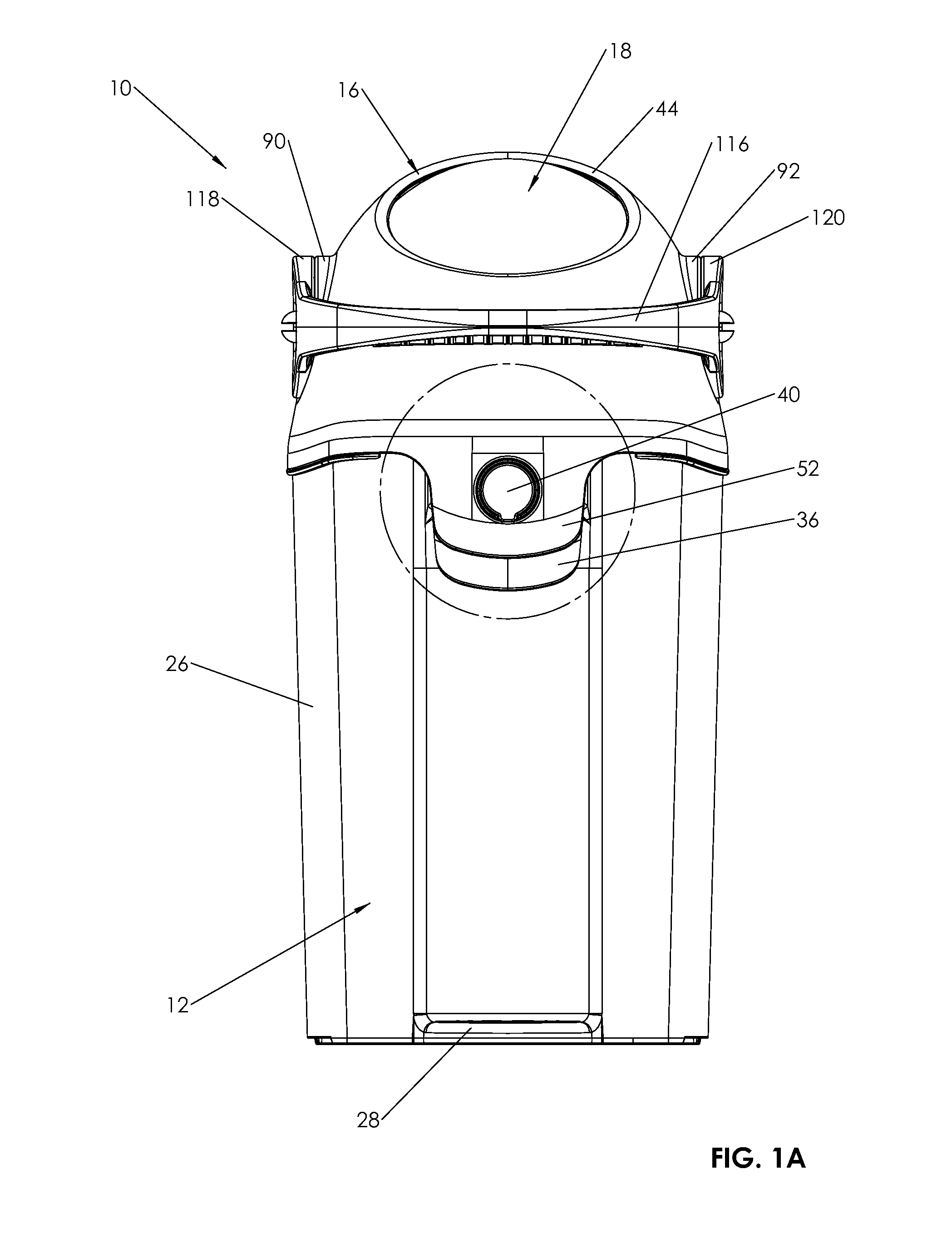
Another example of a shortcoming in the prior art is the prior art devices fail to provide a receptacle assembly which is easily used and cleaned.
However, these known diaper pails contain excessive gaps and holes, particularly in the receptacle assembly and related to providing a door and seal at the top of such assembly, and further related to providing a door and seal at the top.
The '792 publication to Pollack et al, for example, shows a door over the
entry point and various holes and slots immediately adjacent to the location where the diapers are inserted, and insofar as the door is normally closed, it is not possible to easily inspect surface which are most likely to become soiled.
To the extent such products have any more holes, gaps, and slots that are necessary, such products are less able to contain odors and are also harder to keep clean as there is no single smooth, continuous and easily inspected and cleaned surface adjacent the location where the diapers are inserted.
Additionally, known diaper pails often have
doors, protruding rotating drums, and similar mechanical looking components which make it difficult to achieve an attractive and suitably shaped product for use in a nursery.
Finally, there is believed to be a need for an improved diaper pail which provides a receptacle assembly which is free of
doors, protruding rotating drums, and similar mechanical looking components which make the diaper pail look mechanical and thus less suitable for use in a child's nursery.

