
High-heat-retention ladle for carrying molten aluminum

a technology of molten aluminum and ladles, which is applied in the direction of manufacturing converters, manufacturing tools, furniture, etc., can solve the problems of reducing cost efficiency and productivity, high manpower and facilities costs, and casting plants incur a great amount of time and expense, and achieves excellent advantages in terms of productivity, high manpower and facilities costs, and prolonging the cycle of aluminum supply.

Active Publication Date: 2010-12-02
KOREA INST OF IND TECH
View PDF6 Cites 6 Cited by
  • Summary
  • Abstract
  • Description
  • Claims
  • Application Information

AI Technical Summary

Benefits of technology

[0005]Aluminum is used as a component material for a variety of machines such as vehicles and aircraft. Aluminum is generally used in the form of alloys combined with other light metals in order to increase its strength, and aluminum alloys can reduce the weight of products by 50% or more compared to typical steel materials. Therefore, the use of aluminum materials is continuously increasing due to their advantageous effects. For example, aluminum materials can improve performance by decreasing the weight of structures, and can especially reduce the use of energy and the output of pollutants in consideration of high oil prices and environmental problems, which are becoming more important these days.
[0006]A considerable portion (about 40%) of aluminum (alloy) products is produced by a casting method in which raw materials are melted by loading them into a smelter, and then molten metal is formed into a particular shape by pouring it into a mold. The casting method is widely used in the manufacture of components of machines since it has excellent advantages in terms of productivity and size consistency.
[0007]A conventional process of producing products by aluminum casting such as die casting includes first processing of making an aluminum ingot by melting raw materials and second processing of casting final products by melting the aluminum ingot again.
[0008]That is, an aluminum ingot is prepared as an intermediate product by melting an aluminum raw material, which is refined or reproduced in a raw material alloying plant, alloying metals, and the like and pouring molten metal into a mold. Afterwards, a product casting plant produces a final product by again melting the aluminum ingot, which is supplied thereto, and performing a casting process, such as die casting.
[0009]As described above, in the conventional art, aluminum is carried in the form of an ingot to the casting plant even though it is melted in the raw material alloying plant. Therefore, the casting process of making the aluminum ingot in the alloying plant incurs high manpower and facilities costs, and the cycle of supplying aluminum is prolonged, thereby decreasing cost efficiency and productivity.
[0010]The product casting plant also incurs a great amount of time and expense in the process of melting the aluminum ingot again, thereby decreasing cost efficiency and productivity. In addition, a considerable amount of materials is additionally lost due to the oxidation of aluminum during melting. Furthermore, this causes problems of a deteriorated working environment and air pollution in the surroundings since a great amount of dust and pollutants, such as SOx or NOx, is produced.

Problems solved by technology

Therefore, the casting process of making the aluminum ingot in the alloying plant incurs high manpower and facilities costs, and the cycle of supplying aluminum is prolonged, thereby decreasing cost efficiency and productivity.
The product casting plant also incurs a great amount of time and expense in the process of melting the aluminum ingot again, thereby decreasing cost efficiency and productivity.
In addition, a considerable amount of materials is additionally lost due to the oxidation of aluminum during melting.
Furthermore, this causes problems of a deteriorated working environment and air pollution in the surroundings since a great amount of dust and pollutants, such as SOx or NOx, is produced.

Method used


Image

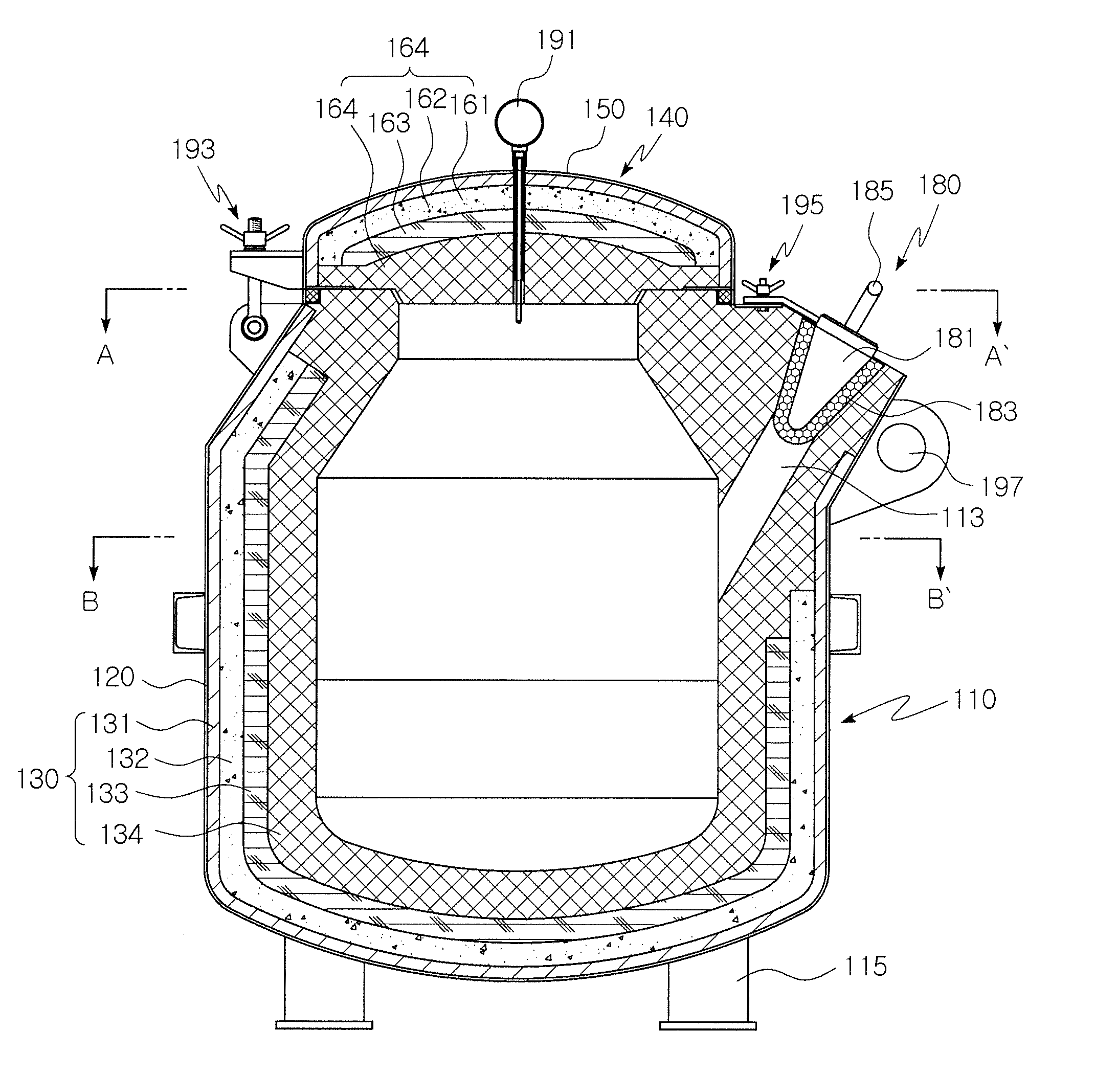
  • High-heat-retention ladle for carrying molten aluminum
  • High-heat-retention ladle for carrying molten aluminum
  • High-heat-retention ladle for carrying molten aluminum

Examples


Embodiment Construction

[0031]Reference will now be made in detail to various embodiments of the present invention(s), examples of which are illustrated in the accompanying drawings and described below. While the invention(s) will be described in conjunction with exemplary embodiments, it will be understood that the present description is not intended to limit the invention(s) to those exemplary embodiments. On the contrary, the invention(s) is / are intended to cover not only the exemplary embodiments, but also various alternatives, modifications, equivalents and other embodiments that may be included within the spirit and scope of the invention as defined by the appended claims.

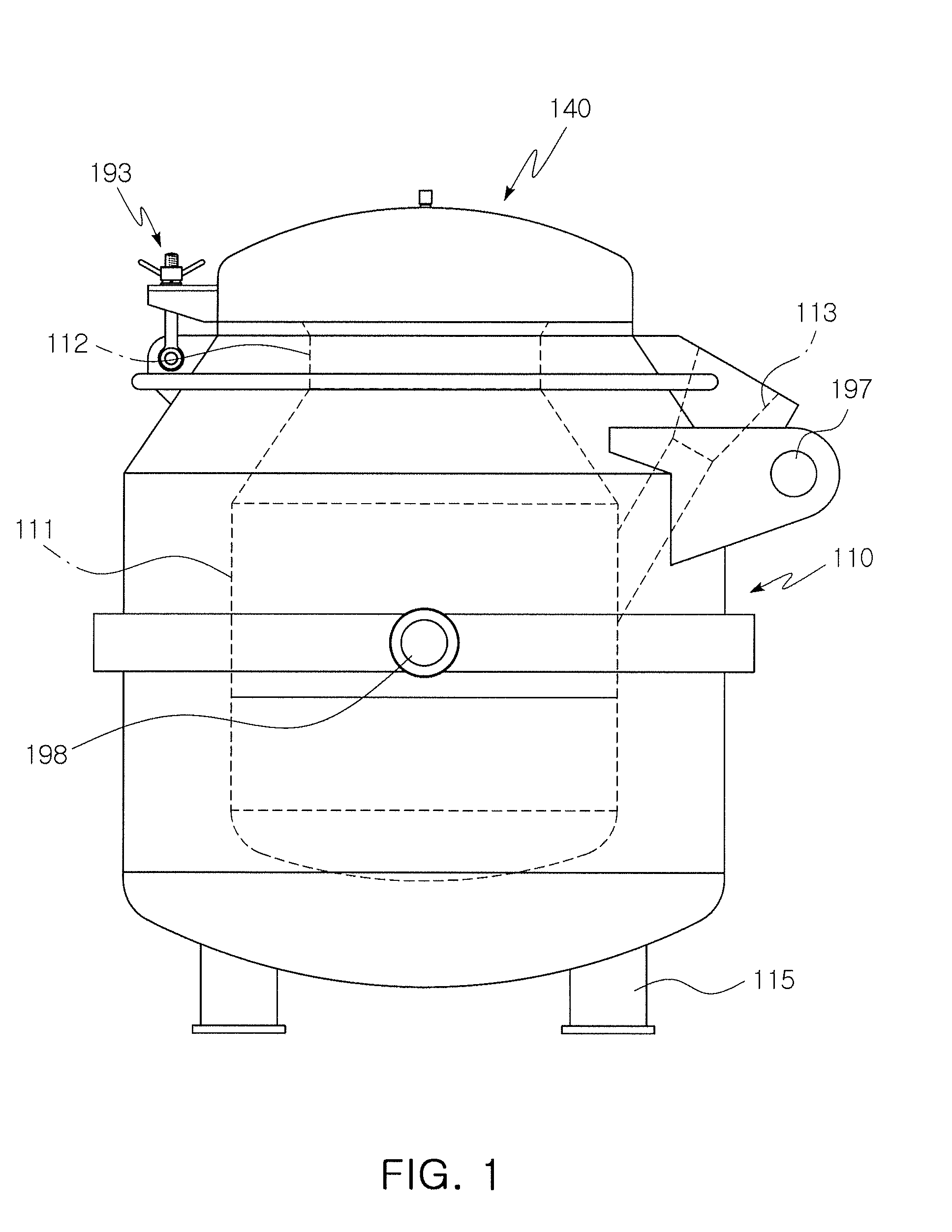
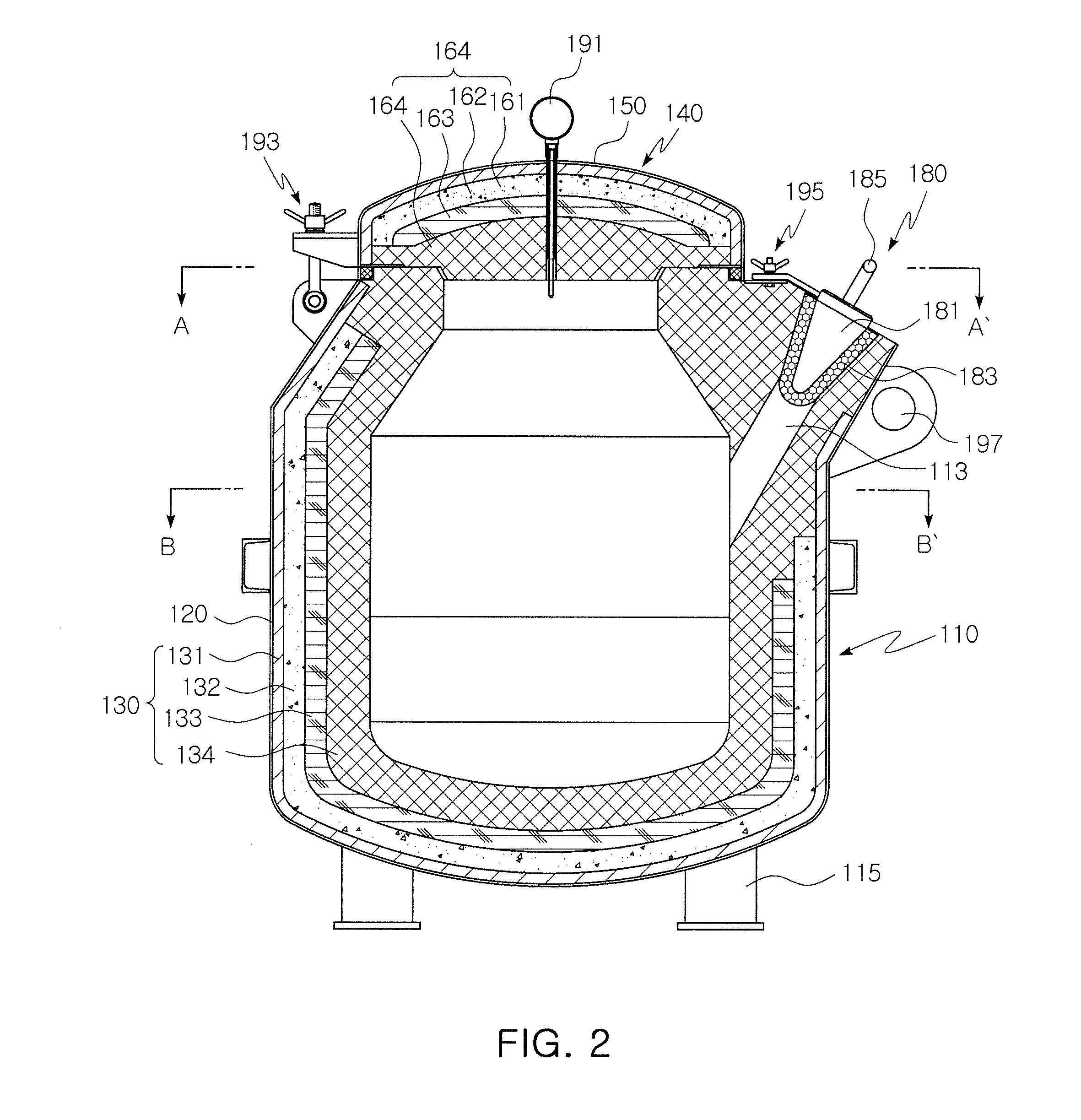
[0032]FIG. 1 is an elevational view showing the outline of a high-heat-retention ladle for carrying molten aluminum according to an exemplary embodiment of the invention, FIG. 2 is a front elevational cross-sectional view showing the ladle shown in FIG. 1, FIG. 3 is a top plan cross-sectional view taken along the line A-A′ in FIG. 2...


PUM

PropertyMeasurementUnit
Cooling rateaaaaaaaaaa
Weightaaaaaaaaaa
Heataaaaaaaaaa

Abstract

A high-heat-retention ladle for carrying molten aluminum includes a ladle body defining therein a storage space, which contains molten aluminum therein, the ladle body including a molten metal inlet and a molten metal outlet, which allow the storage space to communicate with outside, a cover opening and closing the inlet of the ladle body, and a stopper opening and closing the outlet of the ladle body. Each of the ladle body and the cover has an outer shell, which defines a contour thereof, and a multi-layer insulation structure inside the outer shell. The multi-layer insulation structure includes two or more refractory layers. The molten aluminum contained inside the storage space has a temperature drop rate of 5° C. / min or less. It is possible to carry the molten aluminum for a long time in a heat-insulated state and cast a product by directly pouring the molten aluminum into a mold.

Description

CROSS REFERENCE TO RELATED APPLICATION[0001]The present application claims priority from Korean Patent Application Number 10-2009-0046335 filed on May 27, 2009, the entire contents of which application is incorporated herein for all purposes by this reference.BACKGROUND OF THE INVENTION[0002]1. Field of the Invention[0003]The present invention relates to a high-heat-retention ladle for carrying molten aluminum, and more particularly, to a high-heat-retention ladle that can carry molten aluminum for a long time in a heat-insulated state in order to cast a product by directly pouring the molten aluminum into a mold without having to convert raw materials into an ingot and then melt the ingot again.[0004]2. Description of Related Art[0005]Aluminum is used as a component material for a variety of machines such as vehicles and aircraft. Aluminum is generally used in the form of alloys combined with other light metals in order to increase its strength, and aluminum alloys can reduce the w...

Claims


Application Information

Patent Timeline
IPC IPC(8): B22D41/14B22D41/00
CPCB22D41/14B22D41/00B22D41/02B22D11/10B22D21/04C22C1/026
Inventor KIM, EOK SOOHONG, YOUNG MYUNGLIM, KYUNG MOOKCHOI, SOCK HWANPARK, JIN YOUNG
Owner KOREA INST OF IND TECH
Learn More