Curved ion guide with varying ion deflecting field and related methods

a technology of ion guides and ion deflectors, applied in the direction of instruments, particle separator tube details, separation processes, etc., can solve the problems of less than optimal instrument sensitivity, constant dc deflecting field may not work well for ion guides in which ions lose a significant amount of kinetic energy, and constant dc deflecting field may not provide optimal transmission for all of the various ion masses

Active Publication Date: 2010-12-02
AGILENT TECH INC
View PDF17 Cites 49 Cited by
  • Summary
  • Abstract
  • Description
  • Claims
  • Application Information

AI Technical Summary

Benefits of technology

[0009]According to one implementation, an ion guide includes a plurality of curved electrodes and an ion deflection device. The curved electrodes are arranged about a central curved axis, the curved central axis being co-extensive with an arc of a circular section having a radius of curvature. Each electrode is radially spaced from the curved central axis. The electrodes circumscribe a curved ion guide region arranged about the curved central axis. The ion guide region begins at an ion entrance and ends at an ion exit. The ion deflecting device is configured for applying a radial DC electric field across the ion guide region at a magnitude that varies along the curved central axis. The magnitude is at a maximum at the ion entrance and decreases along the curved central axis toward the ion exit.
[0010]According to another implementation, a method is provided for guiding an ion through an ion guide. The ion is transmitted into a curved ion guide region of the ion guide. The ion guide region is circumscribed by a plurality of curved electrodes arranged about a central curved axis, the curved central axis running through the ion guide region co-extensively with an arc of a circular section having a radius of curvature. Each electrode is radially spaced from the curved central axis, wherein the curved ion guide region is arranged about the curved central axis and begins at an ion entrance and ends at an ion exit. A RF electric field is generated across the ion guide region to focus the ion to motions generally along the curved central axis. A DC offset component may also be added in order to control the incoming energy or focusing properties of the ion beam. A radial DC electric field is generated across the ion guide region at a magnitude that varies along the central curved axis to provide an axially varying, radially directed ion deflecting force. The magnitude is at a maximum at the ion entrance and decreases along the curved central axis.

Problems solved by technology

Therefore, in the curved ion guide the ions need to experience a certain minimum amount of RF restoring force during their flight before they move too close to the ion guide rods and become unstable.
In such cases, some of the ions cannot have optimal transmission conditions and they are lost, leading to less than optimal instrument sensitivity.
However, a constant DC deflecting field may not work well for ion guides in which ions lose a significant amount of kinetic energy as they travel through the ion guide, and / or for ion guides in which lower-mass ions are formed in the ion guide and require less deflecting forces than other ions of higher mass that also must be controlled in the same ion guide.
A collision cell may be curved as discussed above for the general case of ion guides, and a curved collision cell presents similar challenges.
It can be seen, then, that a constant DC deflecting field may not provide optimized transmission for all of the various ion masses typically processed in collision cells and like instruments.

Method used


Image

  • Curved ion guide with varying ion deflecting field and related methods
  • Curved ion guide with varying ion deflecting field and related methods
  • Curved ion guide with varying ion deflecting field and related methods

Examples


Embodiment Construction

[0027]The subject matter disclosed herein generally relates to the guiding and deflection of ions and associated ion processing. Examples of implementations of methods and related devices, apparatus, and / or systems are described in more detail below with reference to FIGS. 1-7. These examples are described at least in part in the context of mass spectrometry (MS). However, any process that involves the guiding and deflection of ions may fall within the scope of this disclosure.

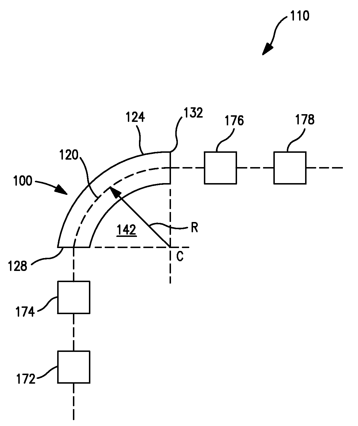
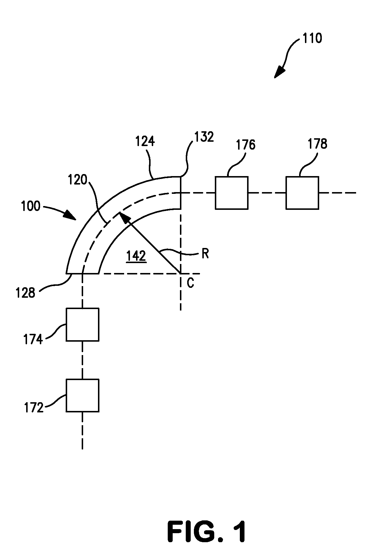
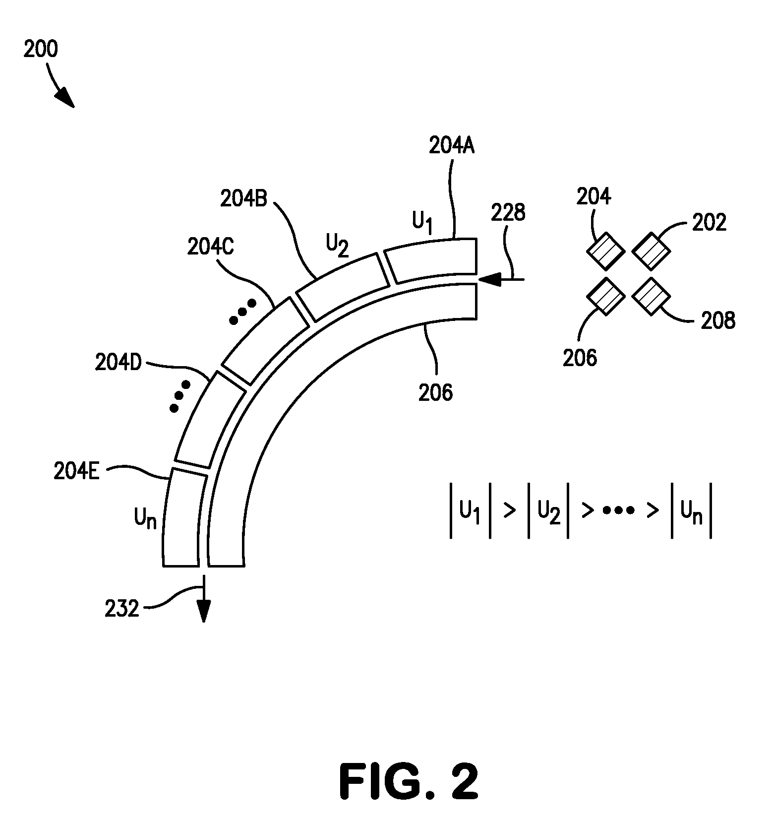
[0028]FIG. 1 is a schematic view of an example of an ion guide (device, apparatus, assembly, etc.) 100, and further of an example of an ion processing system (or device, apparatus, assembly, etc.) 110 that may include the ion guide 100, according to certain implementations of the present disclosure. The ion guide 100 includes a plurality of curved electrodes (see, e.g., FIG. 2) arranged about a curved central axis 120, which may be referred to as the z-axis. The ion guide 100 may generally include a housing or...


PUM


Abstract

An ion guide includes a plurality of curved electrodes and an ion deflecting device. The electrodes are arranged about and radially spaced from a central curved axis, and circumscribe a curved ion guide region from an ion entrance to an ion exit. The ion deflecting device may include a device for applying a DC electric field to one or more electrodes in a radial direction. The magnitude of the DC electric field, and thus the ion deflecting force, varies along the curved axis. The ion guide may for example operate as a collision cell or like instrument.

Description

FIELD OF THE INVENTION[0001]The present invention relates generally to the guiding of ions which finds use, for example, in fields of analytical chemistry such as mass spectrometry. More particularly, the present invention relates to the guiding of ions along a curved path while also subjecting the ions to a varying deflecting electrical field in a radial direction relative to the curved path.BACKGROUND OF THE INVENTION[0002]An ion guide may be utilized to transmit ions in various types of ion processing devices, one example being a mass spectrometer (MS). The theory, design and operation of various types of mass spectrometers are well-known to persons skilled in the art and thus need not be detailed in the present disclosure. A commonly employed ion guide is based on a multipole electrode structure, which may be a RF-only electrode structure in which the ions passing through the ion guide are subjected to a two-dimensional RF electric field that focuses the ions along an axial path...

Claims


Application Information

Patent Timeline
Patent Type & Authority Applications(United States)
IPC IPC(8): H01J3/14H01J49/00
CPCH01J49/421H01J49/063H01J49/22H01J49/26
Inventor MUNTEAN, FELICIAN
Owner AGILENT TECH INC
Why Eureka
Try Eureka